background image

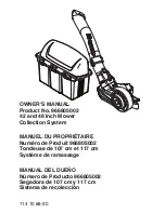
OWNER'S MANUAL

Product No. 966805002

42 and 48 Inch Mower 

Collection System

MANUEL DU PROPRIÉTAIRE

Numéro de Produit 966805002

Tondeuse de 107 cm et 117 cm 

Système de ramassage

MANUAL DEL DUEÑO

Número de Producto 966805002

Segadora de 107 cm y 117 cm 

Sistema de recolección

114 10 68-20

Содержание 966805002

Страница 1: ... 48 Inch Mower Collection System MANUEL DU PROPRIÉTAIRE Numéro de Produit 966805002 Tondeuse de 107 cm et 117 cm Système de ramassage MANUAL DEL DUEÑO Número de Producto 966805002 Segadora de 107 cm y 117 cm Sistema de recolección 114 10 68 20 ...

Страница 2: ...jects thrown into the eyes which can result in severe eye damage ALWAYS wear safety glasses or eye shields before starting the mower and while mowing Standard safety glasses are recommended or a wide vision safety mask for over spectacles CAUTION BEFORE ASSEMBLING GRASS CATCHER TO MOWER Set parking brake Place motion control levers in NEUTRAL position Turn ignition key OFF and remove key Make sure...

Страница 3: ...sy on it do not mow it DO Use extra care with grass catchers or other attachments These can change the stability of the machine Mow up and down slopes 10 Max not across Remove obstacles such as rocks tree limbs etc Watch for holes ruts or bumps Uneven terrain could overturn the machine Tall grass can hide obstacles Use slow speed Choose a low speed so that you will not have to stop while on the sl...

Страница 4: ...hillips Head Screwdriver Hacksaw Pliers Drill and 3 8 drill bit NOTE When the terms RH right hand or LH left hand are used it refers to when the operator is seated on the mower CONTAINER CONTENTS Blower Bagger Assembly Drive Pulley Belt Shield Belt Mounting Brackets Bag of Hardware SAFETY RULES 3 ASSEMBLY 5 OPERATION 9 REPAIR PARTS BLOWER ASSEMBLY 10 BAGGER 12 CHUTES MOUNTS BELTS 14 ...

Страница 5: ...SEMBLY Draw Bar A Original Shoulder Bolt Support Assembly Drawbar A Kit Shoulder Bolt 2 Hang the support assembly over the replacement bolts and align the bottom pin into the drawbar Secure the bottom pin with a hairpin Draw Bar B 1 Slide the flanges of the support assembly in the slots in the drawbar Hairpin Drawbar B Support Assembly Hairpin 2 Pivot the assembly backwards to insert the bottom pi...

Страница 6: ...unt Bracket Contact Area Outer Pulley Cover Pin Hairpin Cotter 1 Locate the rear adjustment nut on the discharge side of the deck To assure the right tighteness mark the front side of the nut 2 Using the mark as a guide turn the nut clockwise 2 1 2 turns with a 3 4 wrench DECK ADJUSTMENT NOTE The kit provides parts for both the 42 and 48 Refer to the parts list for the correct belt for your needs ...

Страница 7: ...pport against bagger inlet flush at outer edges See Illustration 2 Using support as a template drill two 3 8 holes into bagger hood 3 Secure upper chute support to hood with hex bolts washers and nyloc nuts CHUTE SUPPORT NOTE For ease of assembly you may wish assistance from another person for mounting the cover assembly to mower 1 Lift and rotate cover to align the cover brackets with support ass...

Страница 8: ...th the 42 and 48 Use the shorter upper chute for a 42 collection system and the longer upper chute for the 48 1 Slide upper chute onto middle chute lining up the middle chute latch and the acorn nut on the upper chute 2 Stretch bungee latch up onto acorn nut to secure UPPER CHUTE ASSEMBLY CHUTE HOOD INSTALLATION Push upper chute through the gasketed opening in the cover assembly Upper Chute Cover ...

Страница 9: ... e Tip the container on its side and slide the filled bag from the container f Install a new plastic lawn bag with the edges of the bag draped over upper lip of the container g Repeat for all containers h Reinstall containers making sure center containers overlap at center supports i Close cover and secure latches over center support tubes Avoid cutting wet grass or in the morning while the dew is...

Страница 10: ... 1 2 3 4 8 7 23 9 10 11 12 13 14 15 16 17 18 19 20 21 22 6 24 25 26 27 28 29 30 31 32 31 34 35 36 37 39 40 41 42 43 44 45 46 44 48 50 51 52 53 55 56 57 54 55 49 53 38 15 53 44 48 48 48 5 54 52 33 42 47 58 59 REPAIR PARTS ...

Страница 11: ... LATCH HOOD 29 539 11 56 67 1 KEY 3 16 x 1 2 30 539 12 52 29 1 KEY 3 16 x 1 1 2 31 539 13 03 17 1 PIN 32 539 13 03 15 6 HCS 5 16 18 x 1 2 33 539 11 03 21 2 HCS 3 8 24 x 1 1 4 Gr 8 34 539 99 02 09 1 HCS 5 16 18 x 1 35 539 99 06 55 1 HCS 3 8 16 x 1 1 2 36 539 97 69 49 1 HCS 3 8 16 x 1 3 4 37 539 10 84 61 3 HCS 1 2 20 x 1 2 38 539 99 06 43 1 HCS 1 4 20 x 7 8 39 539 99 03 16 4 RHSNB 5 16 18 x 3 4 40 5...

Страница 12: ...12 BAGGER 1 2 3 4 5 6 8 9 10 11 12 17 15 13 14 15 17 18 16 REPAIR PARTS ...

Страница 13: ...9 90 1 FRAME BAGGER 5 532 19 27 09 1 SCREEN COVER 6 532 17 40 83 4 CAP FRAME 8 532 19 25 50 1 SEAL COVER 9 532 19 26 03 1 GASKET COVER 10 539 11 02 81 1 SUPPORT CHUTE 11 539 11 22 94 1 FLEX TRIM 12 532 19 27 86 2 PIN HINGE 13 539 10 80 96 2 HAIR PIN 14 539 99 06 27 2 HCS 5 16 18 x 1 1 4 15 539 97 69 52 6 SCREW 10 24 x 5 8 16 539 11 28 99 2 NUT 5 16 18 HEX FLG NYLOC 17 539 97 69 77 6 NUT 10 24 CROW...

Страница 14: ...14 6 5 14 4 3 13 1 9 2 12 10 7 8 21 11 15 13 16 17 18 19 21 21 18 17 20 REPAIR PARTS CHUTES SUPPORTS COURROIE ...

Страница 15: ... 13 03 47 1 BELT 48 539 13 23 47 1 BELT 42 6 532 19 81 28 1 SUPPORT TUBE ASSY 7 532 19 83 64 1 SUPPORT TUBE ASSY 8 539 13 03 09 1 COVER BELT 9 539 13 03 49 1 DECAL BELT ROUTING 10 539 10 57 43 1 DECAL NO STEP 11 539 10 44 11 1 KNOB w STUD 12 539 10 80 88 1 LATCH CHUTE 13 539 10 80 85 2 SPACER SPLIT 14 532 17 69 97 2 BOLT 3 8 16 SHOULDER 15 539 97 69 52 1 SCREW 10 24 x 625 MACH 16 539 10 80 81 1 SC...

Страница 16: ...orter une visière écran ou des lunettes de protection standard MISE EN GARDE AVANT DE MONTER LE COLLECTEUR D HERBE SUR LA TONDEUSE Engager le frein de stationnement Mettez les leviers de commande de la transmission au POINT MORT Tournez la clé de contact en position d arrêt OFF et enlevez la clé Veillez à ce que les lames et toutes les pièces mobiles soient complètement arrêtées MISE EN GARDE N ut...

Страница 17: ... effectuer la tonte À FAIRE Soyez particulièrement prudent avec le ramasse herbe et les autres accessoires Ceux ci peuvent changer la stabilité de la machine Tondez les pentes en montant ou en descendant max 10 mais jamais perpendiculairement à la déclivité Enlevez les obstacles tels que pierres branches d arbres etc Faites attention aux trous aux ornières ou aux bosses Un terrain irrégulier peut ...

Страница 18: ... à métaux Pinces Mèche et foret de 3 8 po CONTENU DU CARTON Souffleur ensacheur Poulie d entraînement Protège courroie Courroie Supports de montage Sac des pièces REMARQUE L utilisation des termes RH côté droit ou LH côté gauche correspond à la position de l opérateur assis sur la tondeuse REGLAS DE SEGURIDAD 17 MONTAGE 19 UTILISATION 23 PIÈCES DE RECHANGE 24 MONTAGE DU SOUFFLEUR 24 MONTAGE DU BAC...

Страница 19: ...emble de soutien aux boulons de remplacement et alignez la goupille du bas dans la barre d attelage Fixez la goupille du bas avec une goupille fendue Barre D attelage B 1 Faites glisser les brides de l ensemble de soutien dans les encoches de la barre d attelage Goupille Goupille 2 Faites pivoter l ensemble vers l arrière pour insérer la goupille du bas dans la barre d attelage Fixez la goupille d...

Страница 20: ...veiller à ce qu il soit bien serré marquez le devant de l écrou 2 En prenant la marque comme repère tournez l écrou dans le sens horaire de 2 1 2 tours avec une clé de 3 4 po RÉGLAGE DU CHÂSSIS REMARQUE Le kit comprend des pièces pour les systèmes de 42 po et de 48 po Reportez vous à la liste des pièces pour choisir la courroie qui convient à vos besoins 1 Placez la courroie au dessus de la poulie...

Страница 21: ...ensacheur tout contre les bords extérieurs 2 En utilisant le support comme gabarit percer deux trous de 3 8 po dans le capot de l ensacheur 3 Fixer le support de la goulotte supérieure au capot au moyen de boulons rondelles et écrous SUPPORT DE GOULOTTE REMARQUE Pour faciliter le montage du couvercle sur la tondeuse demandez de l aide à une autre personne 1 Soulevez et tournez le couvercle pour al...

Страница 22: ...42 po et de 48 po Utilisez la goulotte supérieure plus courte pour le système de ramassage de 42 po et la goulotte supérieure plus longue pour le système de 48 po 1 Insérez la goulotte supérieure dans la glissière intermédiaire en alignant le loquet de la glissière intermédiaire et l écrou borgne sur la goulotte supérieure 2 Étirez le verrou élastique jusqu à l écrou borgne puis engagez le ENSEMBL...

Страница 23: ...le e Basculez le bac sur son côté et faites glisser le sac poubelle plein hors du bac f Mettez en place un nouveau sac poubelle avec les bords du sac drapés sur le bord supérieur du bac g Répéter les instructions ci dessus pour tous les bacs h Remettez en place les bacs mais veillez à faire chevaucher le bac de droite et le bac de gauche sur le support central i Fermez le couvercle et fixez les lo...

Страница 24: ...PIÈCES DE RECHANGE 1 2 3 4 8 7 23 9 10 11 12 13 14 15 16 17 18 19 20 21 22 6 24 25 26 27 28 29 30 31 32 31 34 35 36 37 39 40 41 42 43 44 45 46 44 48 50 51 52 53 55 56 57 54 55 49 53 38 15 53 44 48 48 48 5 54 52 33 42 47 58 59 ...

Страница 25: ... 31 539 13 03 17 1 GOUPILLE 32 539 13 03 15 6 VIS HCS 5 16 18 x 1 2 33 539 11 03 21 2 VIS HCS 3 8 24 x 1 1 4 GR 8 34 539 99 02 09 1 VIS HCS 5 16 18 x 1 35 539 99 06 55 1 VIS HCS 3 8 16 x 1 1 2 36 539 97 69 49 1 VIS HCS 3 8 16 x 1 3 4 37 539 10 84 61 3 VIS HCS 1 4 20 x 1 2 38 539 99 06 43 1 VIS HCS 1 4 20 x 7 8 39 539 99 03 16 4 BOULON 5 16 18 x 3 4 40 539 99 06 45 1 BOULON 3 8 16 x 1 41 539 99 02 ...

Страница 26: ...26 MONTAGE DU BACS PIÈCES DE RECHANGE 1 2 3 4 5 6 8 9 10 11 12 17 15 13 14 15 17 18 16 ...

Страница 27: ...OINT DE COUVERCLE 10 539 11 02 81 1 SUPPORT GOULOTTE 11 539 11 22 94 1 GARNITURE SOUPLE 12 532 19 27 86 2 GOUPILLE BRIDE 13 539 10 80 96 2 GOUPILLE 14 539 99 06 27 2 VIS HCS 5 16 18 x 1 1 4 15 539 97 69 52 6 VIS Nº 10 24 x 5 8 16 539 11 28 99 2 ÉCROU 5 16 18 NYLOC 17 539 97 69 77 6 ÉCROU Nº 10 24 AUTO SERRANT 18 539 99 01 88 4 RONDELLE 5 16 SAE RÉF PIÈCE N N QTÉ DESCRIPTION RÉF PIÈCE N N QTÉ DESCR...

Страница 28: ...28 PIÈCES DE RECHANGE 6 5 14 4 3 13 1 9 2 12 10 7 8 21 11 15 13 16 17 18 19 21 21 18 17 20 GOULOTTE SUPPORTS COURROIE ...

Страница 29: ... 539 13 03 09 1 COUVERCLE COURROIE 9 539 13 03 49 1 AUTOCOLLANT ACHEMINEMENT DE LA COURROIE 10 539 10 57 43 1 AUTOCOLLANT NE PAS MONTER 11 539 10 44 11 1 BOUTON AVEC GOUJON 12 539 10 80 88 1 LOQUET DE GLISSIÈRE 13 539 10 80 85 2 ENTRETOISE FENDUE 14 532 17 69 97 2 BOULON 3 8 16 À ÉPAULEMENT 15 539 97 69 52 1 VIS 10 24 x 0 625 MACH 16 539 10 80 81 1 VIS 10 14 x 1 2 SPÉCIALE 17 539 10 80 83 2 VIS 10...

Страница 30: ...d y durante el corte del césped Se recomiendan gafas de seguridad estándares o una máscara de seguridad de visión amplia sobre los anteojos PRECAUCIÓN ANTES DEL MONTAJE DEL RECOGEDOR DE CÉSPED EN EL CORTACÉSPED Accione el freno de estacionamiento Coloque las palancas de control de movimiento en la posición NEUTRA Gire la llave de encendido a la posición APAGADO y saque la llave Asegúrese de que la...

Страница 31: ...ACER Tenga mucho cuidado con los recogedores de césped o con otros accesorios Estos pueden afectar la estabilidad de la máquina Pode las pendientes hacia arriba y hacia abajo a 10 como máximo no de un lado a otro Retire los obstáculos como rocas ramas etc Tenga cuidado con los huecos surcos o irregularidades El terreno disparejo podría volcar la máquina El césped alto puede ocultar obstáculos Util...

Страница 32: ...adro y broca de 3 8 CONTENIDO DEL CONTENEDOR NOTA Cuando se utilicen los términos DERECHA lado derecho o IZQUIERDA lado izquierdo se refiere a cuando el operador está sentado en el cortacésped REGLAS DE SEGURIDAD 31 MONTAJE 33 OPERACIÓN 37 PARTES DE REPARACIÓN MONTAJE DE SOPLADORA 38 MONTAJE DE RECOGEDOR 40 CONDUCTO SOPORTES CORREA 42 Montaje de sopladora y recogedor Protección de la correa Soport...

Страница 33: ...junto de soporte 2 Cuelgue el montaje del soporte sobre los pernos de reemplazo y alinee el pasador inferior con la barra de tracción Asegure el pasador inferior con una horquilla Barra De Tracción B 1 Deslice las bridas del conjunto de soporte en las ranuras de la barra de tracción 2 Pivotee el conjunto hacia atrás para insertar el pasador inferior en la barra de tracción Asegure el pasador infer...

Страница 34: ... la polea exterior Pasado Horquilla 1 Localice la tuerca de ajuste trasera en el lado de descarga del equipo Para garantizar el apriete correcto marque la parte delantera de la tuerca 2 Utilizando la marca como guía gire la tuerca en el sentido de las agujas del reloj dos vueltas y media con una llave de 3 4 AJUSTE DEL EQUIPO NOTA El kit proporciona piezas para 42 y 48 Consulte el listado de pieza...

Страница 35: ...erior contra la entrada del recogedor a ras de los bordes exteriores 2 Utilice el soporte como plantilla taladre dos orificios de 3 8 en la cubierta del recogedor 3 Asegure el soporte del conducto superior a la cubierta con arandelas tuercas y pernos SOPORTE DEL CONDUCTO NOTA La ayuda de otra persona puede facilitar el montaje del conjunto de la cubierta al cortacésped 1 Levante y gire la cubierta...

Страница 36: ...más corto para un sistema de recolección de 42 y el conducto superior más largo para un sistema de recolección de 48 1 Deslice el conducto superior sobre el conducto de la parte media alineando el pestillo del conducto de la parte media y la tuerca ciega del conducto superior 2 Expanda la correa elástica que se engancha en la tuerca ciega para asegurar MONTAJE DEL CONDUCTO SUPERIOR INSTALACIÓN DEL...

Страница 37: ...llena del contenedor f Instale una nueva bolsa de plástico para césped con los bordes de la bolsa envueltos sobre el labio superior del contenedor g Repita el proceso para todos los contenedores h Vuelva a instalar los contenedores asegurándose de que el contenedor derecho se traslapa con el contenedor izquierdo en los soportes centrales i Cierre la tapa y asegure los enganches sobre los tubos de ...

Страница 38: ...ARTES DE REPARACIÓN 1 2 3 4 8 7 23 9 10 11 12 13 14 15 16 17 18 19 20 21 22 6 24 25 26 27 28 29 30 31 32 31 34 35 36 37 39 40 41 42 43 44 45 46 44 48 50 51 52 53 55 56 57 54 55 49 53 38 15 53 44 48 48 48 5 54 52 33 42 47 58 59 ...

Страница 39: ... 539 13 21 24 1 PLACA RESPALDO 27 539 13 21 22 1 PLACA RESPALDO 28 539 10 80 88 1 SEGURO CUBIERTA 29 539 11 56 67 1 LLAVE 3 16 x 1 2 30 539 12 52 29 1 LLAVE 3 16 x 1 1 2 31 539 13 03 17 1 PASADOR 32 539 13 03 15 6 HCS 5 16 18 x 1 2 33 539 11 03 21 2 HCS 3 8 24 x 1 1 4 Gr 8 34 539 99 02 09 1 HCS 5 16 18 x 1 35 539 99 06 55 1 HCS 3 8 16 x 1 1 2 36 539 97 69 49 1 HCS 3 8 16 x 1 3 4 37 539 10 84 61 3 ...

Страница 40: ...40 MONTAJE DE RECOGEDOR PARTES DE REPARACIÓN 1 2 3 4 5 6 8 9 10 11 12 17 15 13 14 15 17 18 16 ...

Страница 41: ...OGEDOR 4 532 17 69 90 1 BASTIDOR RECOGEDOR 5 532 19 27 09 1 REJILLA CUBIERTA 6 532 17 40 83 4 TAPA BASTIDOR 8 532 19 25 50 1 SELLO CUBIERTA 9 532 19 26 03 1 JUNTA CUBIERTA 10 539 11 02 81 1 SOPORTE CONDUCTO 11 539 11 22 94 1 FLEX TRIM 12 532 19 27 86 2 PASADOR BISAGRA 13 539 10 80 96 2 HORQUILLA 14 539 99 06 27 2 HCS 5 16 18 x 1 1 4 15 539 97 69 52 6 TORNILLO 10 DE 24 x 5 8 16 539 11 28 99 2 TUERC...

Страница 42: ...42 PARTES DE REPARACIÓN 6 5 14 4 3 13 1 9 2 12 10 7 8 21 11 15 13 16 17 18 19 21 21 18 17 20 CONDUCTO SOPORTES CORREA ...

Страница 43: ...ECCIÓN CORREA42 5 539 13 03 47 1 CORREA 48 539 13 23 47 1 CORREA 42 6 532 19 81 28 1 MONTAJE DE TUBO DE SOPORTE 7 532 19 83 64 1 MONTAJE DE TUBO DE SOPORTE 8 539 13 03 09 1 CUBIERTA CORREA 9 539 13 03 49 1 ETIQUETA COLOCACIÓN DE LA CORREA 10 539 10 57 43 1 ETIQUETA NO PISAR 11 539 10 44 11 1 PERILLA CON ESPÁRRAGO 12 539 10 80 88 1 SEGURO CONDUCTO 13 539 10 80 85 2 SEPARADOR DIVIDIDO 14 532 17 69 9...

Страница 44: ...11 20 2018 CL ...

Отзывы: