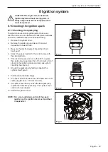
WARNING: The fuel used in this product
and the fuel vapor are dangerous. They can
cause eye and skin irritation, breathing
problems and are highly flammable.
9.1 Description
The figures in this description do not correspond with the
carburettor on the product. They show only the principle
of design and function.
9.2 Design
The carburettor is based on 5 sub-systems:
Pump unit, A.
Metering unit, B.
Mixing unit, C.
Air valve unit, D
Autotune unit, AV
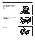
In the pump unit (A), fuel is pumped from the fuel tank to
the metering unit of the carburettor. One side of the
pump diaphragm is connected to the crankcase and
pulses in crank case effects pump diaphragm with the
pressure changes in the crankcase. With the help of inlet
and outlet check valves in diaphragm, the fuel is
transferred through a filter screen to the inlet needle. See
figure 1.
The Autotune unit (AV) is attached to the metering unit
(B). Here the correct quantity of fuel is adjusted for the
actual speed and power output. See figure 1.
The mixing unit (C) houses the choke valve, the throttle
valve and the diffuser jets. Here air is mixed with the fuel
to give a fuel/air mixture that can be ignited by the
ignition spark. See figure 1.
9.3 Function
The carburettor operates differently in the following
modes:
• Start mode
• Idling mode
• Part throttle mode
• Full throttle mode
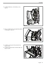
In Start mode the choke valve (see fig. 2 E) is completely
shut. This increases the vacuum in the carburettor and
fuel is easier to suck from all the diffuser jets. The throttle
valve (F) is partly open. The air throttle valve (D) is
closed .
Carburettor
9 Carburettor
AV
AIR/FUEL MIX
FUEL
AIR
A
D
B
C
AV
AIR/FUEL MIX
FUEL
AIR
E
F
D
Fig. 1
Fig. 2
English – 29
Содержание 545FX AT
Страница 1: ...Workshop manual English 545RXT AT 545FX AT 545FXT AT 545FX 545FXT 545RX 545RXT ...
Страница 2: ......
Страница 8: ...Service tools 3 Service tools 3 mm 4 mm 5 mm 1 11 4 6 9 7 10 8 5 2 12 3 13 14 15 16 17 8 English ...
Страница 79: ...English 79 ...
Страница 80: ...2018 10 04 115 88 11 26 ...

