background image

7

ASSEMBLY / PRE-OPERATION

CHECK TIRE PRESSURE

The tires on your snow thrower were overinflated at the fac-

tory for shipping purposes.  Correct and equal tire pres sure 

is important for best snow throwing performance.
•  Reduce tire pressure to 14-17 PSI (19-24.5 N-m).

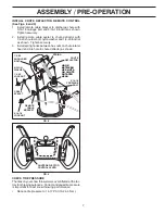
INSTALL CHUTE DEFLECTOR REMOTE CONTROL 

(See Figs. 8 and 9)

1.  Install remote cable bracket to discharge chute with

5/16-18 carriage bolt and 5/16-18 locknut as shown.  

Tighten securely.

2.  Install remote cable eyelet to chute deflector with

1/4-20 shoulder bolt, nylon washer and 1/4-20 locknut 

as shown.  Tighten securely.

3.  Install spring hooks between hex nuts on chute rotater 

head and into hole in chute deflector as shown.

CHUTE DEFLECTOR 

CONTROL LEVER

FIG. 9

HOOK

BE TWEEN 

HEX NUTS

ON CHUTE

ROTATER 

HEAD

SPRING

CHUTE

DE FLEC TOR

5/16-18 

CARRIAGE 

BOLT

5/16-18

LOCKNUT

REMOTE 

CABLE 

BRACKET

1/4-20 

LOCK NUT

CABLE

EYELET

NYLON 

WASHER

1/4-20 

SHOULDER 

BOLT

FIG. 8

Содержание 10527SB-LS

Страница 1: ...10527SB LS Owner s Manual 96193003700 ...

Страница 2: ... the machine Operation 1 Do not put hands or feet near or under rotating parts Keep clear of the discharge opening at all times 2 Exercise extreme caution when operating on or cross ing gravel drives walks or roads Stay alert for hidden hazards or traffic 3 After striking a foreign object stop the engine motor remove the wire from the spark plug disconnect the cord on electric motors thoroughly in...

Страница 3: ...e machine at high transport speeds on slippery surfaces Look behind and use care when operating in reverse 13 Disengage power to the collector impeller when snow thrower is transported or not in use 14 Use only attachments and accessories approved by the manufacturer of the snow thrower such as wheel weights counterweights or cabs 15 Never operate the snow thrower without good visibility or light ...

Страница 4: ...assemble must be tightened securely Use the correct tools as necessary to ensure proper tightness REMOVE SNOW THROWER FROM CARTON 1 Remove all accessible loose parts and parts boxes from carton ASSEMBLY PRE OPERATION 2 Cut down all four corners of carton and lay panels flat 3 Removethetwo 2 screwssecuringtheaugerhousing to the pallet 4 Remove all packing materials except plastic tie holding speed ...

Страница 5: ...ner spring SPEED CONTROL ROD HANDLE KNOB LOWER HANDLE PLASTIC TIE UPPER HANDLE FIG 1 INSTALL TRACTION DRIVE CONTROL ROD See Figs 3 and 4 The traction drive control rod has the long loop on the end of the spring as shown 1 Slide rubber sleeve up rod and hook end of spring into pivot bracket with loop opening down as shown 2 With top end of rod positioned under left side of control panel push rod do...

Страница 6: ...ket 4 Install 3 8 washer and locknut on threaded stud and tighten securely AUGER CONTROL ROD CONTROL ARM RUBBER SLEEVE LOOP OPENING UP FIG 5 INSTALL AUGER CONTROL ROD See Figs 5 and 6 The auger control rod has the short loop on the end of the spring as shown 1 Slide rubber sleeve up rod and hook end of spring into control arm with loop opening up as shown 2 With top end of rod positioned under rig...

Страница 7: ...charge chute with 5 16 18 carriage bolt and 5 16 18 locknut as shown Tighten securely 2 Install remote cable eyelet to chute deflector with 1 4 20 shoulder bolt nylon washer and 1 4 20 locknut as shown Tighten securely 3 Install spring hooks between hex nuts on chute rotater head and into hole in chute deflector as shown CHUTE DEFLECTOR CONTROL LEVER FIG 9 HOOK BETWEEN HEX NUTS ON CHUTE ROTATER HE...

Страница 8: ...s Save this manual for future reference These symbols may appear on your snow thrower or in literature supplied with the product Learn and understand their meaning FORWARD PRIMER IGNITION KEY INSERT TO START AND RUN PULL OUT TO STOP READ AND FOLLOW ALL SAFETY INFORMATION AND INSTRUCTIONS BEFORE USE OF THIS PRODUCT KEEP THESE INSTRUCTIONS FOR FUTURE REFERENCE DANGER OR WARNING REVERSE SNOW DISCHARG...

Страница 9: ...ng the engine Recoil auxiliary starter handle used for starting the engine Primer pumps additional fuel from the carburetor to the cylinder for use when starting a cold engine Choke control used for starting a cold engine LH and RH turn triggers used to steer the snow thrower MEETS A N S I SAFETY REQUIREMENTS Our snow throwers conform to the standards of the American National Standards Institute T...

Страница 10: ...to raise the deflector and increase the distance Move lever back to lower the deflector and decrease the distance Be sure lever springs back and locks into desired position FIG 13 DISCHARGE CHUTE CONTROL LEVER CHUTE DEFLECTOR REMOTE CONTROL LEVER The operation of any snow thrower can result in foreign objects thrown into the eyes which canresultinsevereeyedamage Alwayswear safety glasses or eye sh...

Страница 11: ...e before restarting engine Restart the engine then squeeze the auger control lever to the handle to clear snow from the auger hous ing and the discharge chute DRIVE SPEED CONTROL LEVER TRACTION DRIVE CONTROL LEVER FIG 16 CLEAN OUT TOOL FIG 15 MOUNTING CLIP DISCHARGE CHUTE POWER STEERING OPERATION See Fig 17 Steering triggers are used to assist in steering your snow thrower The triggers are located...

Страница 12: ...L FILL CAP DIPSTICK PRIMER SAFETY IGNITION KEY ON OFF SWITCH CHOKE CONTROL STARTER BUTTON RECOIL STARTER HANDLE GASOLINE FILLER CAP NOTE ALL ITEMS ARE SHOWN IN THEIR TYPICAL LOCATION ACTUAL LOCATION MAY VARY WITH ENGINE ON YOUR UNIT FIG 20 BEFORE STARTING THE ENGINE CHECK ENGINE OIL LEVEL See Fig 20 The engine on your snow thrower has been shipped from the factory already filled with oil 1 Check e...

Страница 13: ...Over priming may cause flooding preventing the engine from starting If you do flood the engine wait a few minutes before attempting to start and DO NOT push the primer 5 Pull recoil starter handle quickly Do not allow starter rope to snap back 6 Whentheenginestarts releasetherecoilstarterhandle and slowly move the choke control to the OFF posi tion Allow the engine to warm up for a few minutes Eng...

Страница 14: ... schedule in this manual NOTE Use only Original Equipment Manufacturer OEM parts to service this unit Failure to do so can cause the unit to malfunction and pose a risk of injury to the operator BEFORE EACH USE 1 Check engine oil level 2 Check for loose fasteners 3 Checkcontrolstobesuretheyarefunctioningproperly LUBRICATION Keep your snow thrower well lubricated See LUBRICATION CHART SNOW THROWER ...

Страница 15: ...nnot come in contact with plug 2 Clean area around drain plug 3 Remove drain plug and drain oil in a suitable container 4 Install drain plug and tighten securely 5 Wipe off any spilled oil from snow thrower and engine 6 Install left wheel if removed for draining oil Be sure to install klick pin into proper hole in wheel axle See TO REMOVE WHEELS in the Service and Adjustments section of this manua...

Страница 16: ...th two 2 capscrew shear bolts and hex nuts Should a foreign object or ice become lodged in the impeller the capscrews are designed to break preventing damage to any other com ponents If impeller does not turn when auger control lever is engaged check to see if the capscrews have sheared To replace the capscrew shear bolts 1 Disengage all controls and move throttle control to STOP position Wait for...

Страница 17: ...s be replaced by a qualified service centre department NOTE It is recommended that both the auger and traction drive belt be replaced at the same time TheV beltsonyoursnowthrowerareofspecialconstruction andshouldbereplacedbyoriginalequipmentmanufacturer OEM belts available from your nearest qualified service centre department Using other than OEM belts can cause personal injury or damage to the sn...

Страница 18: ...or Do not empty the gas tank and carburetor if using fuel stabilizer ENGINE OIL Drain oil with engine warm and replace with clean engine oil See ENGINE in the Maintenance section of this manual CYLINDER 1 Remove spark plug 2 Pour one ounce 29 ml of oil through spark plug hole into cylinder 3 Pull recoil starter handle slowly a few times to distribute oil 4 Replace with new spark plug OTHER Remove ...

Страница 19: ...s in FULL position 1 Move choke to OFF position runs roughly 2 Blockage in fuel line 2 Clean fuel line 3 Stale fuel 3 Empty fuel tank carburetor refill with fresh clean gasoline 4 Water in fuel 4 Empty fuel tank carburetor refill with fresh clean gasoline 5 Carburetor is in need of 5 Contact a qualified service centre adjustment or overhaul Excessive 1 Loose parts or damaged 1 Tighten all fastener...

Страница 20: ...1 11 3 12 12 4 13 14 15 17 8 7 11 5 6 11 16 18 35 19 21 22 23 24 25 23 22 21 20 36 26 27 28 30 29 31 31 32 33 34 01 07 004 B NOTE All component dimensions given in U S inches 1 inch 25 4 mm IMPORTANT Use only Original Equipment Manufacturer O E M replacement parts Failure to do so could be hazardous damage your snow thrower and void your warranty ...

Страница 21: ... 874 78 04 26 SCREW 1 4 20 X 625 11 532 15 53 77 NUT 5 16 18 12 532 16 31 83 SCREW 5 16 18 X 625 13 819 11 15 07 WASHER 14 810 04 05 00 LOCKWASHER 5 16 15 874 94 05 16 SCREW 5 16 18 X 1 00 16 532 18 03 55 CARRIAGE BOLT 17 532 19 41 89 SCREW 13 16 X 625 18 532 40 77 60 PLUG 19 532 40 77 61 GEARBOX COVER RH 20 532 40 77 66 GASKET 21 532 40 77 70 SEAL 22 532 40 77 62 BEARING 23 532 17 46 97 THRUST WA...

Страница 22: ... mm IMPORTANT Use only Original Equipment Manufacturer O E M replacement parts Failure to do so could be hazardous damage your snow thrower and void your warranty 1 2 3 1 2 3 01 07 007 A 1 532 18 81 70 PLASTIC RETAINER 2 532 41 18 33 AUGER BALL BEARING 3 532 17 95 82 SCREW 5 16 18 X 1 00 1 2 3 5x 4 5x 01 07 022 B 1 532 42 21 40 AUGER HOUSING 2 532 40 77 27 SCRAPPER BAR 3 872 27 05 05 CARRIAGE BOLT...

Страница 23: ... 532 40 78 34 SKID PLATE 2 872 27 05 06 CARRIAGE BOLT 5 16 18 X 750 3 532 75 11 53 NUT 5 16 18 NOTE All component dimensions given in U S inches 1 inch 25 4 mm IMPORTANT Use only Original Equipment Manufacturer O E M replacement parts Failure to do so could be hazardous damage your snow thrower and void your warranty 1 2 01 07 015 A 1 532 42 21 42 AUGER ASSEMBLY 27 LH 2 532 42 21 43 AUGER ASSEMBLY...

Страница 24: ...mm IMPORTANT Use only Original Equipment Manufacturer O E M replacement parts Failure to do so could be hazardous damage your snow thrower and void your warranty 1 2 5 3 4 3 4 1 2 5 3 4 3 4 01 16 001 A KEY PART NO NO DESCRIPTION 1 532 18 47 47 DRIFT CUTTER BAR 2 872 27 05 06 CARRIAGEBOLT5 16 18X 750 3 532 17 92 46 PLASTIC WASHER 4 810 04 05 00 LOCKWASHER 5 16 5 532 12 86 38 NUT 5 16 18 ...

Страница 25: ...LECTOR WELDMENT 3 532 42 11 63 DEFLECTOR CONTROL ASSEMBLY 4 532 42 03 25 DEFLECTOR SEAL 5 532 41 42 80 KNOB BLACK 6 532 12 84 15 POP RIVET 7 817 50 10 10 SCREW 10 24 X 625 8 532 41 98 21 CHUTE SNOW SHIELD 9 532 42 17 28 SHIELD RETAINER STRAP 10 532 17 98 29 SHOULDER BOLT 1 4 20 X 375 11 532 17 92 46 PLASTIC WASHER 12 532 19 17 30 NUT 1 4 20 13 872 25 05 05 CARRIAGE BOLT 3 8 16 X 625 14 532 75 11 5...

Страница 26: ...us damage your snow thrower and void your warranty KEY PART NO NO DESCRIPTION 1 2 2 3 6 6 4 5 01 09 008 B 1 532 42 11 60 LEVER CABLE ROTATOR ASSEMBLY GRAY 2 817 50 10 10 SCREW 10 24 X 625 3 532 42 06 78 ROTATOR HEAD 4 532 42 11 61 ROTATOR PIVOT BRACKET 5 532 42 06 75 PULLEY PIVOT 6 532 42 11 62 CABLE ASSEMBLY GRAY NOTES 1 ITEMS INDICATED WITH AN ARE LISTED AS REFERENCE FOR SERVICE PARTS ONLY 1 2 0...

Страница 27: ...IPTION KEY PART NO NO DESCRIPTION 2 4 4 4 3 3 1 4 01 05 006 A 1 532 42 17 05 LOWER TUBE GRAY 2 532 41 54 89 PIVOT SUPPORT 3 532 15 00 78 BOLT 5 16 18 X 500 4 817 00 06 16 SCREW 3 8 16 X 1 00 1 2 3 4 6 6 7 7 8 8 8 9 9 5 5 10 10 01 08 011 A 1 532 42 17 08 PLOW HANDLE LH 2 532 42 17 09 PLOW HANDLE RH 3 532 19 69 44 PANEL BRACKET LH 4 532 19 69 43 PANEL BRACKET RH 5 532 41 45 15 HEATED HANDLE GRIP 6 8...

Страница 28: ...anty KEY PART NO NO DESCRIPTION 1 4 5 6 7 7 8 10 11 14 14 12 13 13 12 2 3 9 9 8 01 08 012 A 1 532 41 55 39 CONTROL PANEL 2 532 42 17 06 CONTROL LEVER LH 3 532 42 17 07 CONTROL LEVER RH 4 532 41 55 46 TRACTION ROD ARM 5 532 42 14 92 IMPELLER ROD ARM 6 532 41 26 77 INTERLOCK ROD 7 532 42 16 13 SPACER CONTROL LEVER 8 532 16 96 75 RETAINER 9 817 06 04 08 SCREW 1 4 20 X 50 10 532 41 42 80 KNOB BLACK 11...

Страница 29: ...IPTION 1 532 18 04 80 IMPELLER ROD ASSEMBLY 2 532 40 57 40 TRACTION ROD ASSEMBLY 3 532 18 04 45 SHIFTER ROD TOP 4 532 18 77 16 SHIFTER ROD BOTTOM 5 532 18 04 47 SPRING SLEEVE 6 532 17 86 69 IMPELLER SPRING 7 532 18 09 26 TRACTION SPRING 8 872 27 05 06 CARRIAGE BOLT 5 16 18 X 750 9 532 15 53 77 NUT 5 16 18 10 532 16 96 75 RETAINER 11 532 40 33 00 CLUTCH ROD 12 532 41 69 21 REAR PLATE 13 532 41 54 3...

Страница 30: ...RT NO NO DESCRIPTION KEY PART NO NO DESCRIPTION 1 2 3 4 5 6 01 08 007 B 1 532 41 62 88 INTERLOCK SPRING 2 532 41 45 72 INTERLOCK CAM 3 532 17 88 31 TORSION SPRING 4 532 16 96 75 RETAINER 5 817 06 04 10 SCREW 1 4 20 X 625 6 532 42 18 14 INTERLOCK STOP 1 4 4 5 5 2 3 8 6 7 01 10 010 A 1 532 42 13 51 CONSOLE PANEL GRAY 2 532 42 14 48 HEADLIGHT BEZEL GRAY 3 532 17 86 66 HALOGEN HEADLIGHT 4 532 18 44 71...

Страница 31: ...w thrower and void your warranty 1 17490508 BOLT 5 16 18 X 500 2 751153 NUT 5 16 18 3 180017 FLANGE BEARING 4 73930500 NUT 5 16 18 5 198176 RUBBER WHEEL PLATE 6 179831 RUBBER WHEEL RING 7 178613 RUBBER WHEEL HUB 8 74760514 BOLT 5 16 18 X 875 9 175344 TRUNNION BEARING ASSEMBLY 10 12000012 RETAINER 11 180066 HEX SHAFT 12 180065 PINION GEAR 13 192616 AUXILIARY PLATE 14 179270 SPACER PLATE 15 180082 I...

Страница 32: ... 14 15 15 16 17 8 17 18 19 20 21 26 23 27 22 13 15 24 25 28 33 32 30 31 29 14 15 15 34 35 36 37 38 39 41 20 32 40 43 41 20 32 42 44 NOTE All component dimensions given in U S inches 1 inch 25 4 mm IMPORTANT Use only Original Equipment Manufacturer O E M replacement parts Failure to do so could be hazardous damage your snow thrower and void your warranty ...

Страница 33: ... SHIFTER SUPPORT BRACKET 12 178695 PIN 13 85179 RETAINER 14 17490408 SCREW 1 4 20 X 500 15 17490508 BOLT 5 16 18 X 500 16 175338 DRIVE MOUNT PLATE 17 155377 NUT 5 16 18 18 191080 TRACTION PULLEY 19 19111507 WASHER 20 10040500 LOCKWASHER 5 16 21 74950512 SCREW 5 16 18 X 750 22 419925 IDLER BRAKE ARM 23 180523 IDLER PULLEY 24 175324 IDLER PIVOT BRACKET 25 175330 PIN 26 74780524 SCREW 5 16 18 X 1 50 ...

Страница 34: ... E M replacement parts Failure to do so could be hazardous damage your snow thrower and void your warranty 1a 1b 1b 4 3 3 4 6 7 7 8 5 6 2 01 03 001 A 1 532 40 49 23 assy of 1a 1b AXLE ASSEMBLY 1a 532 40 43 07 AXLE SHAFT 1b 532 18 42 06 ROLL PIN 3 16 2 532 18 00 81 GEAR 3 532 17 46 97 THRUST WASHER 4 532 17 98 30 AXLE BEARING 5 532 14 63 15 SCREW 5 16 18 X 625 6 817 49 05 08 BOLT 5 16 18 X 500 7 53...

Страница 35: ...e hazardous damage your snow thrower and void your warranty KEY PART NO NO DESCRIPTION 1 2 3 4 4 5 5 6 6 01 00 016 A KEY PART NO NO DESCRIPTION 1 2 3 4 01 04 003 A ENGINE B S MODEL 20M314 1237 E1 1 532 41 53 40 FRAME 2 532 41 08 77 BOTTOM PAN 3 532 41 70 71 ENGINE MOUNT PLATE 4 532 15 04 06 BOLT 3 8 16 5 532 15 00 78 SCREW 5 16 18 X 750 6 532 18 44 71 SCREW 10 24 X 625 1 532 19 22 13 COVER ASSEMBL...

Страница 36: ...RIPTION 1 532 40 51 61 COVER 2 532 18 44 71 SHOULDER SCREW 3 812 00 00 45 RETAINER RING 4 532 19 21 26 WHEEL DRIVER 5 532 18 24 66 RETAINER RING 6 532 18 76 22 WHEEL LOBE 7 532 19 49 41 CLUTCH SLIDE 8 532 17 91 39 SPRING 9 532 18 92 82 SQUARE KEY 10 532 19 49 40 AXLE LOBE 11 532 17 46 97 THRUST WASHER 12 532 19 95 19 STEERING YOKE 13 532 18 41 97 STEERING BRACKET 14 817 49 05 08 SCREW 5 16 18 X 50...

Страница 37: ... only Original Equipment Manufacturer O E M replacement parts Failure to do so could be hazardous damage your snow thrower and void your warranty KEY PART NO NO DESCRIPTION KEY PART NO NO DESCRIPTION 1 2 01 15 002 A 1 532 41 52 63 STEER CABLE BRACKET LH 2 532 18 78 59 STEER CABLE BRACKET RH 1 2 01 06 005 A 1 532 19 94 99 WHEEL 16 X 4 80 X LH 2 532 19 95 00 WHEEL 16 X 4 80 X RH ...

Страница 38: ...N KEY PART NO NO DESCRIPTION 1 01 14 007 A 1 2 3 4 5 6 7 8 9 10 11 14 12 13 01 14 003 A 1 532 19 85 63 POWER CORD 2 532 16 96 75 RETAINER PIN 3 532 18 06 84 WRENCH 4 532 18 45 05 REMOTE SPRING 5 532 17 98 29 SHOULDER BOLT 1 4 20 6 532 17 92 46 NYLON WASHER 1 4 20 7 532 19 17 30 LOCKNUT 1 4 20 8 872 25 05 05 CARRIAGE BOLT 5 16 18 X 5 8 9 532 75 11 53 LOCKNUT 5 16 18 10 873 80 06 00 LOCKNUT 3 8 16 1...

Страница 39: ...93003700 PRODUCTNO 9619300 37 1 532 18 10 37 DECAL DANGER 2 532 42 37 10 DECAL AUGER 10527SB LSb HUSQ USA 3 532 18 10 35 DECAL DANGER DEFLECTOR 4 532 18 10 42 DECAL DANGER 5 532 42 37 09 DECAL CONSOLE 10527SB LSb HUSQ USA 6 532 18 10 33 DECAL INSTRUCTION 7 532 41 54 55 DECAL AUTOMATIC 9 532 41 54 75 DECAL SPEED CONTROL 10 532 18 37 30 DECAL REMOTE DEFLECTOR 11 532 41 53 99 DECAL LH TRIGGER 12 532 ...

Страница 40: ...t time of purchase SECTION 2 HUSQVARNA S OBLIGATIONS UNDER THE WARRANTY Husqvarna will repair or replace defective components without charge for parts or labor if a component fails because of a defect in material or workmanship during the warranty period SECTION 3 ITEMS NOT COVERED BY THIS WARRANTY The following items are not covered by this warranty 1 Normal customer maintenance items which becom...

Отзывы: