Bath Ventilator with Light
Owner’s Manual
The Garden District Collection
43053-01
20110908
©2011 Hunter Fan Co.
Model
80707
English
Espa
ñol
Página 21
Страница 1: ...Bath Ventilator with Light Owner s Manual The Garden District Collection 43053 01 20110908 2011 Hunter Fan Co Model 80707 English Español Página 21 ...
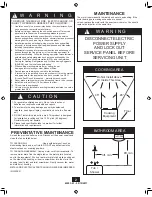
Страница 2: ...including fire rated construction 4 Sufficient air is needed for proper combustion and exhausting of gasses through the flue chimney of fuel burning equipment to prevent backdrafting Follow the heating equipment manufacturer s guideline and safety standards such as those published by the National Fire Prevention Association NFPA and the American Society for Heating Refrigeration and Air Conditioni...
Страница 3: ...1 000 x2 x2 M 66534 01 000 I 74508 53 000 x2 G 03242 07 133 K 74508 53 000 B C I x2 B C I x2 Check all the parts If damaged call 1 888 830 1326 for replacements Tools Needed Estimated assembly time 30 to 60 minutes Not included B C 3 8 Cable Connector Extra Screws I x2 NOTE Strain relief cable connector must be installed Not Included S 65517 01 000 T 88432 01 000 ...
Страница 4: ... the pre loaded screw tips until flush with the side of the housing Turn off the power source Remove the motor blower from the housing Remove the pre loaded screw tip covers Before Installation NOTE Remove all packing materials before installation 1 H E 3 2 H I I 4 5 6 ...
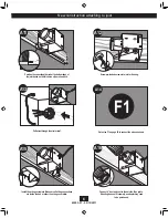
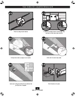
Страница 5: ...o to step B11 page 9 For Existing Construction accessible from above go to step C11 page 12 For Existing Construction accessible only from below go to step D11 page 16 Remove the wiring cover Insert the strain relief into the housing and secure with the washer Remove the wiring cover screw Pop out the first wiring access slug Use second if needed 7 8 9 10 B ...
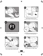
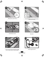
Страница 6: ... the outside Tape joints If ducting does not fit securely an adapter may need to be purchased Position the correct depth mark at the bottom edge of the joist based on the thickness of your sheetrock Pull wires through the strain relief Install the wiring cover plate Make sure all wiring connections are inside the box or under the wiring cover plate 5 8 1 2 A11 A12 A13 F1 A14 A15 0 A16 ...
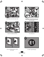
Страница 7: ... up into position Make sure the wires are not pinched between the motor and the housing Turn on the power source Go to step E1 on page 18 to attach grill Connect wiring from the motor to the wiring cover plate Secure the motor by tightening the 2 screws Test the motor If the motor does not run check the plug connection E1 A22 ...
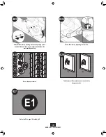
Страница 8: ...th mark at the bottom edge of the joist based on the thickness of your sheetrock Drill a hole in the center of each outline Attach the rails onto the screws Slide the mounting rails into brackets Mark position of screws by using holes as a template Insert screws leaving space between the screw head and the joist Screws are not provided ...
Страница 9: ...all the wiring cover plate Make sure all wiring connections are inside the box or under the wiring cover plate Tighten screws Connect 4 duct and vent to the outside Tape joints If ducting does not fit securely an adapter may need to be purchased F1 Go to step F1 on page 20 to connect the wires as shown B19 Connect wiring from the motor to the wiring cover plate ...
Страница 10: ...ushing up into position Make sure the wires are not pinched between the motor and the housing Turn on the power source Go to step E1 on page 18 to attach grill Secure the motor by tightening the 2 screws Test the motor If the motor does not run check the plug connection E1 B27 B26 ON OFF ...
Страница 11: ... mounting rails into brackets Mark position of screws by using holes as a template Remove an existing fan and check to make sure the opening is largeenoughtoaccommodatethenewmotorhousing 8 x8 5 Cut out an opening for the housing Position the correct depth mark at the bottom edge of the joist based on the thickness of your sheetrock 8 8 5 C12 5 8 1 2 5 8 1 2 C13 C14 ...
Страница 12: ...are not provided Tighten screws Pull wires through the strain relief Drill a hole in the center of each outline Connect 4 duct and vent to the outside Tape joints If ducting does not fit securely an adapter may need to be purchased Attach the rails onto the screws 1 8 Bit C15 C16 C17 C18 C19 C20 ...
Страница 13: ...ten the strain relief screws Reinstall the motor by inserting the tabs and pushing up into position Make sure the wires are not pinched between the motor and the housing Install the wiring cover plate Make sure all wiring connections are inside the box or under the wiring cover plate Go to step F1 on page 20 to connect the wires as shown F1 C22 C21 ...
Страница 14: ...43053 01 09 12 2011 14 C27 C28 Turn on the power source Go to step E1 on page 18 to attach grill Test the motor If the motor does not run check the plug connection E1 C29 C28 ON OFF ...
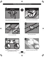
Страница 15: ...connector Tape joints If ducting does not fit securely an adapter may need to be purchased Removeanexistingfanandchecktomakesuretheopeningis largeenoughtoaccommodatethenewmotorhousing 8 x8 5 Pull wires through strain relief Install the housing flush with the sheetrock and secure by tightening the pre loaded screws into the joist Go to step F1 on page 20 to connect the wires as shown F1 D16 ...
Страница 16: ...un check the plug connection Secure the motor by tightening the 2 screws Install the wiring cover plate Reinstall the motor by inserting the tabs and pushing up into position Make sure the wires are not pinched between the motor and the housing Connect wiring from the motor to the wiring cover plate ON OFF D22 ...
Страница 17: ...iefbracketscrew Feed the mounting cable through the hiding plate then attach mounting cable a to the support bracket Align posts B and D stamped into motor housing with posts B and D stamped into light fixture Slide support bar and hiding plate onto posts NOTE The grill s size shape and number of lights may vary Raise the bezel onto the threaded rod of the support bracket E6 Attaching the grill ...
Страница 18: ...ete Unscrew glass retainer ring using the glass ring tool provided Screw finial onto the threaded rod of the support bracket Connect wires as shown F1 F A Fan Motor Light 2 Pin Black Ground Green Bare Copper White Black Main Switch 1 AC In Black Switch 2 AC In Black Light Option White White 3 Pin Option Fan Main Light Together Wiring the fan ...
Страница 19: ...nnections to be sure they are secure Check the wiring to make sure it matches the wiring diagram Solution Replace the light bulb with a new bulb Turn power on replace fuse or reset breaker Check all plug connections to be sure they are secure Check the wiring to make sure it matches the wiring diagram Solution Check and tighten all fasteners Check the glass to make sure it is secure Check the flap...
Страница 20: ...T LIMITED TO ANY IMPLIED WARRANTY OF MERCHANTABILITY OR FITNESS FOR A PARTICULAR PURPOSE IN RESPECT TO ANY HUNTER FAN FAN BATH EXHAUST FAN MOTOR OR OTHER FAN PART IS EXPRESSLY LIMITED TO THE PERIOD OF THE EXPRESS WARRANTY SET FORTH ABOVE FOR SUCH MOTORS OR OTHER PARTS This warranty is voided if your Hunter Fan bath exhaust fan is not purchased and installed in the U S A This warranty excludes and ...
Страница 21: ...Ventilador para baño con luz Manual del Propietario The Garden District Collection 43053 02 20110909 2011 Hunter Fan Co Modelo 80707 Español ...
Страница 22: ...e la Asociación Nacional de Protección contra Incendios NFPA la Asociación de Ingenieros Americanos en Calefacción y Aire acondicionado ASHRAE y los códigos locales 5 Al cortar o taladrar en paredes o techo no dañe el cableado eléctrico u otros servicios no visibles 6 Los ventiladores canalizados siempre deben descargar al aire libre 7 Si va a instalar esta unidad en una bañera o ducha debe tener ...
Страница 23: ...242 07 133 K 74508 53 000 B C I x2 Verifique todos los componentes Si están dañados llame al 1 866 405 3814 para obtener un reemplazo B C Conector de cable de 3 8 Tornillos adicionales I x2 NOTA Debe estar instalado el manguito de alivio de tensión del cable No incluido Herramientas necesarias no suministradas Tiempo estimado de ensamblaje entre 30 y 60 minutos No incluido B C I x2 S 65517 01 000 ...
Страница 24: ... precargadas hasta que estén a nivel con el lado del alojamiento Apague la fuente de alimentación Retirer le moteur souffleur du boîtier Retire las cubiertas de las puntas de tornillo precargadas Antes de la instalación NOTA Retire todo el material de embalaje antes de la instalación 1 H E 3 2 H I I 4 5 6 ...
Страница 25: ...mer tapón metálico de acceso del cableado Utilice el segundo si es necesario 7 8 9 10 B Escoja la opción de instalación Para constricción nueva fijación a la viga vaya al paso A11 página 7 Para construcción nueva suspendido entre vigas vaya al pasa B11 página 9 Para construcción existente accesible desde arriba vaya al paso C11 página 12 Para construcción existente accesible sólo desde abaja vaya ...
Страница 26: ...as las conexiones de cableado estén dentro de la caja o debajo de la placa de cubierta del cableado 5 8 1 2 A11 A12 A13 F1 A14 A15 0 A16 Conecte un ducto de 4 y ventile hacia el exterior Aplique cinta a las uniones Si el ducto no se ajusta firmemente puede ser necesario comprar un adaptador Ubique la correcta marca de profundidad en el borde inferior de la viga según el espesor de su plancha de ye...
Страница 27: ...pladorintroduciendolaspestañas ylevantandoasuposición Asegúresequelosalambresnose pellizquenentreelmotorsopladoryelalojamiento Asegure el motor soplador apretando los 2 tornillos Encienda la fuente de alimentación Pruebe el motor soplador Si el motor soplador no funciona verifique la conexión del enchufe Vaya al paso E1 en la página 18 para fijar la rejilla A21 Encendido Apagado ...
Страница 28: ...profundidad en el borde inferior de la viga según el espesor de su plancha de yeso Marque la posición de los tornillos utilizando los agujeros como una plantilla Marque la posición de los tornillos utilizando los agujeros como una plantilla Introduzca los tornillos dejando espacio entre la cabeza del tornillo y la viga No se proporcionan los tornillos Fije los rieles con los tornillos ...
Страница 29: ...ina 20 para onnectoer les fils tel qu indequé comme indiqué Instale la placa de cubierta del cableado Asegúrese que todas las conexiones de cableado estén dentro de la caja o debajo de la placa de cubierta del cableado Conecte un ducto de 4 y ventile hacia el exterior Aplique cinta a las uniones Si el ducto no se ajusta firmemente puede ser necesario comprar un adaptador Conecte el mazo de cables ...
Страница 30: ...ón Asegúresequelosalambresno sepellizquenentreelmotor sopladoryelalojamiento Asegure el motor soplador apretando los 2 tornillos Encienda la fuente de alimentación Pruebe el motor soplador Si el motor soplador no funciona verifique la conexión del enchufe Vaya al paso E1 en la página 18 para fijar la rejilla Encendido Apagado ...
Страница 31: ...e para acomodar el alojamiento del motor soplador nuevo 8 pulg x 8 1 2 pulg Utilice el alojamiento del motor soplador como una plantilla para marcar la posición Recorte una abertura para el alojamiento Deslice los rieles de montaje en los soportes Ubique la correcta marca de profundidad en el borde inferior de la viga según el espesor de su plancha de yeso Marque la posición de los tornillos utili...
Страница 32: ... entre la cabeza del tornillo y la viga No se proporcionan los tornillos Fije los rieles con los tornillos Apriete los tornillos Conecte un ducto de 4 y ventile hacia el exterior Aplique cinta a las uniones Si el ducto no se ajusta firmemente puede ser necesario comprar un adaptador Tienda los cables a través del manguito de alivio de tension ...
Страница 33: ...l cableado Asegúrese que todas las conexiones de cableado estén dentro de la caja o debajo de la placa de cubierta del cableado Conecte el mazo de cables NO PERMITAQUE EL MOTOR SOPLADOR CUELGUE DEL MAZO DE CABLES Vuelvaainstalarelmotor sopladorintroduciendolaspestañas ylevantandoasuposición Asegúresequelosalambresnose pellizquenentreelmotor sopladoryelalojamiento Asegure el motor soplador apretand...
Страница 34: ... 34 C27 C28 E1 C29 Encienda la fuente de alimentación Pruebe el motor soplador Si el motor soplador no funciona verifique la conexión del enchufe Vaya al paso E1 en la página 18 para fijar la rejilla C28 Encendido Apagado ...
Страница 35: ... pulg Mueva el alojamiento a su posición encima del techo Tienda los cables a través del manguito de alivio de tension Conecte el ducto existente con el conector de ducto Aplique cinta a las uniones Si el ducto no se ajusta firmemente puede ser necesario comprar un adaptador Instale el alojamiento a nivel con la plancha de yeso y asegúrelo apretando los tornillos precargados en la viga Vaya al pas...
Страница 36: ... de cables NO PERMITAQUE EL MOTOR SOPLADOR CUELGUE DEL MAZO DE CABLES Vuelvaainstalarelmotor sopladorintroduciendolaspestañas ylevantandoasuposición Asegúresequelosalambresnose pellizquenentreelmotor sopladoryelalojamiento Asegure el motor soplador apretando los 2 tornillos Encienda la fuente de alimentación Pruebe el motor soplador Si el motor soplador no funciona verifique la conexión del enchuf...
Страница 37: ...artefactodeiluminación Deslicelabarra desoporteylaplacaencubridorahastalospostes Pase el cable de montaje de a través de la placa encubridora luego fije el cable de montaje a en el soporte de apoyo Conecte el manojo de alambres Introduzcalapestañaenángulodelsoportedelaliviadorde tensionesparaqueseengancheenelbordedelmotor Reinstale eltornillodelsoportedelaliviadordetensiones Levante el bisel hasta...
Страница 38: ...anillo suministrada Coloque la pantalla en los portalámparas y reinstale los anillos de retención de la pantalla usando la herramienta para el anillo Completo Conecte los alambres como se muestra F2 F A Motor del ventilador Luz 2 clavijas 3 clavijas Negro Tierra Verde Cobre desnudo Blanco Negro Interruptor principal 1 CA Negro Interruptor 2 CA Negro Luz Opción Blanco Blanco Opción Ventilador y luz...
Страница 39: ... conexiones de los enchufes para asegurarse que estén firmes Verifique el cableado para asegurarse que coincida con el diagrama de cableado Solución Reemplace la bombilla con una nueva Encienda la alimentación eléctrica reemplace el fusible o restablezca el interruptor automático Verifique todas las conexiones de los enchufes para asegurarse que estén firmes Verifique el cableado para asegurarse q...
Страница 40: ...ARANTIE TIENT LIEU DE TOUT AUTRE GARANTIE EXPRESSE LA DURÉE DE TOUTE GARANTIE IMPLICITE INCLUANT MAIS SANS Y ÊTRE LIMITÉE UNE QUELCONQUE GARANTIE IMPLICITE DE QUALITÉ MARCHANDE OU DE COMPATIBILITÉ À UN USAGE PARTICULIER EST EXPRESSÉMENT LIMITÉE À LA PÉRIODE DE LA GARANTIE EXPRESSE ÉNONCÉE PLUS HAUT POUR LES MOTEURS ET AUTRES PIÈCES Cette garantie est nulle si votre ventilateur n a pas été acheté e...