Hunter 36 • Waste and Sanitation Systems
10.5
ing tank in the waters you occupy. Some areas have restric-
tions on pumping out black water waste!
10.4 Head System
All vessels with fixed toilets that are operated on the
waterways of the United States and some foreign coun-
tries are required to be equipped with an operable Marine
Sanitation Device (MSD). The Marine Sanitation System
aboard your boat is a waste tank system defined by the
United States Coast Guard as a Type III System. Type
III systems permit operation of the toilet without direct
discharge of untreated waste after every flush. Type III
systems can be discharged at a Marina, Dockside Pump-
out stations or, if in coastal waters, at least three miles
offshore.
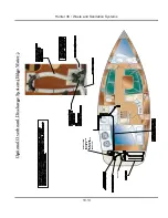
Note: Overboard discharge capabilities must remain inoperative
while within the 3 mile limit. This is accomplished by closing the
macerator discharge through hull valve. Refer to the Mechanical
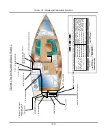
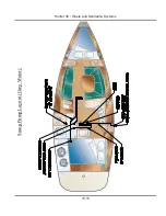
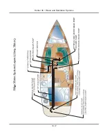
Arrangement illustration in the Boating Safety Section or the
Sanitation Arrangement illustration at the end of this section.
10.4.1 Electric Head System
These heads are typically designed to use fresh water.
There is a discharge. Between the toilet and the waste
tank is a device called a macerator that is not totally unlike
a blender or a garbage disposal in that it purees solid
waste and paper. Macerating heads require more flush
water than any other type of toilet, a minimum of 1 gallon
to rinse urine completely out of the machinery, a minimum
of 3 gallons of clear solids and paper. Insufficient flushing
shortens the life of the motor and macerator.
The 12 volt electric marine toilet comes with a compact
white vitreous china bowl and is equipped with a dual
function pump which eliminates having to mess with
hand pumps and dry bowl valves. With the simple push
of a single switch, the self-priming flush pump rinses the
bowl.
The toilet is controlled by a switch at the MDP. Refer to
the electrical sections of this manual for more information
about MDP. Refer to the location illustrations in this sec-
tion or the Boating Safety section for location information
of your sanitation system.
In Fig. 10.6, you will find a general outline illustration for
the Electric Head systems. This illustrations will give you
an idea about the components in the system and the rout-
ing of the waste lines.
Wastes tank
Macerator
Electric Head System
Overboard
Discharge
Fresh Water
Supply
Switch
Toilet
Fig. 10.6
CAUTION
!
!
Do not use chlorine-based or caustic cleaning
agents, or chemicals such as a drain opening prod-
uct in your head systems. Use of these products
may cause serious damage to the system’s seals
and hoses.
10.5 Operations and Maintenance
This section details the system’s operation and mainte-
nance on the components or systems if applicable.
10.5.1 Bilge Pumps
As we previously discussed in this section and in the
DC Electric Systems Section, your boat has a total of
two bilge pumps. The Emergency, or High Water Pump
(optional), and the standard bilge pump. We detailed the
operations of these pumps in the DC Electric Section
(Section 7).
Here are the steps mentioned in that subject:
10.5.1.1 To manually operate your bilge pumps:
Note: The power to the MDP does not need to be energized in
order to manually operate your bilge pumps.
1. Locate the bilge pump switches at the MDP and switch
them to the manual position.
2. Another procedure to be used in extreme circumstanc-
es involves locating the float switch and manually rotating
Содержание H36
Страница 1: ...Operator s Operator s Manual Manual H36 H36 V1 040107 P N 1031378 ...
Страница 2: ......
Страница 9: ...Introduction Introduction H36 H36 Chapter 1 Chapter 1 V1 040107 P N 1031378 ...
Страница 14: ...Hunter 36 Introduction 1 6 Notes ...
Страница 15: ...V1 040107 P N 1031378 and Documents Documents Forms Forms H36 H36 Chapter 2 Chapter 2 ...
Страница 26: ...Hunter 36 Documents and Forms Maintenance Log Date Maintenance Performed Hourmeter 2 12 ...
Страница 27: ...Hunter 36 Documents and Forms 2 13 Date Maintenance Performed Hourmeter Maintenance Log ...
Страница 30: ...Hunter 36 Documents and Forms Power Squadron recommendations for maintenance and safe boating 2 16 ...
Страница 31: ...Hunter 36 Documents and Forms 2 17 Local sailing club or marina s recommendations for maintenance and up keep ...
Страница 33: ...Hunter 36 Documents and Forms 2 19 Spare Parts List ...
Страница 34: ...Hunter 36 Documents and Forms Dates of practice drills and onboard safety inspections 2 20 ...
Страница 35: ...Hunter 36 Documents and Forms 2 21 My personal preferences for maintenance items safety gear ...
Страница 36: ...Hunter 36 Documents and Forms Notes 2 22 ...
Страница 37: ...DC 071609 Limited Limited Warranty Warranty Chapter 3 Chapter 3 ...
Страница 38: ...This Page Intentionally Left Blank Hunter Limited Warranty 3 2 ...
Страница 47: ...Boating Boating Safety Safety H36 H36 Chapter 4 Chapter 4 V1 040107 P N 1031378 ...
Страница 68: ...Hunter 36 Boating Safety 4 22 Notes ...
Страница 69: ...Chapter 5 Chapter 5 Fuel Fuel Systems Systems H36 H36 V1 040107 P N 1031378 ...
Страница 75: ...Fig 5 7 A Quick Fuel Filter Reference Hunter 36 Fuel Systems 5 7 ...
Страница 82: ...Notes Hunter 36 Fuel Systems 5 14 ...
Страница 83: ...Underwater Underwater Gear Gear H36 H36 Chapter 6 Chapter 6 V1 040107 P N 1031378 ...
Страница 92: ...Hunter 36 Underwater Gear 6 10 Notes ...
Страница 93: ...DC Electric DC Electric Systems Systems H36 H36 Chapter 7 Chapter 7 V1 040107 P N 1031378 ...
Страница 103: ...Hunter 36 DC Electric 7 11 7 8 BASIC DC POWER SUPPLY SYSTEM DIAGRAM ...
Страница 104: ...Hunter 36 DC Electric 7 12 Notes ...
Страница 106: ...Hunter 36 DC Electric 7 14 Notes ...
Страница 108: ...Hunter 36 DC Electric 7 16 Notes ...
Страница 109: ...AC Electric AC Electric Systems Systems H36 H36 Chapter 8 Chapter 8 V1 040107 P N 1031378 ...
Страница 118: ...This Page Intentionally Left Blank Hunter 36 AC Electric Systems 8 10 ...
Страница 119: ...Hunter 36 AC Electric Systems 8 11 7 8 AC DC Electric Power Supply Diagram pp y g ...
Страница 120: ...Hunter 36 AC Electric Systems 8 12 This Page Intentionally Left Blank ...
Страница 121: ...Hunter 36 AC Electric Systems 8 13 Notes ...
Страница 122: ...Hunter 36 AC Electric Systems 8 14 Notes ...
Страница 123: ...Water Water Systems Systems H36 H36 Chapter 9 Chapter 9 V1 040107 P N 1031378 ...
Страница 130: ...Hunter 36 Water Systems 9 8 This Page Intentionally Left Blank ...
Страница 132: ...Hunter 36 Water Systems 9 10 This Page Intentionally Left Blank ...
Страница 133: ...Hunter 36 Water Systems 9 11 Notes ...
Страница 134: ...Hunter 36 Water Systems 9 12 Notes ...
Страница 135: ...Waste Waste Systems Systems H36 H36 Chapter 10 Chapter 10 V1 040107 P N 1031378 ...
Страница 144: ...This Page Intentionally Left Blank Hunter 36 Waste and Sanitation Systems 10 10 ...
Страница 146: ...This Page Intentionally Left Blank Hunter 36 Waste and Sanitation Systems 10 12 ...
Страница 148: ...This Page Intentionally Left Blank Hunter 36 Waste and Sanitation Systems 10 14 ...
Страница 149: ...Sump Pump Layout Grey Water p p y y Hunter 36 Waste and Sanitation Systems 10 15 ...
Страница 150: ...This Page Intentionally Left Blank Hunter 36 Waste and Sanitation Systems 10 16 ...
Страница 152: ...This Page Intentionally Left Blank Hunter 36 Waste and Sanitation Systems 10 18 ...
Страница 153: ...Hunter 36 Waste and Sanitation Systems 10 19 Notes ...
Страница 154: ...Hunter 36 Waste and Sanitation Systems 10 20 Notes ...
Страница 155: ...and Engines Engines Transmissions Transmissions H36 H36 Chapter 11 Chapter 11 V1 040107 P N 1031378 ...
Страница 164: ...Hunter 36 Engines and Transmissions 11 10 This Page Intentional Left Blank ...
Страница 165: ...V1 040107 P N 1031378 Sails Sails Rigging H36 H36 Chapter 12 Chapter 12 and and ...
Страница 171: ...Hunter 36 Sails and Rigging 12 7 Standing Rigging Details Standard ...
Страница 172: ...Hunter 36 Sails and Rigging 12 8 Standing Rigging Details Furling ...
Страница 173: ...Hunter 36 Sails and Rigging 12 9 Mast Upper Spreader Tip Details pp p p H A B C D E F G ...
Страница 174: ...Hunter 36 Sails and Rigging 12 10 C A B D E F G H J K I Mast Lower Spreader Tip Details p p ...
Страница 175: ...Hunter 36 Sails and Rigging 12 11 Standing Rigging Details ...
Страница 179: ...Hunter 36 Sails and Rigging 12 15 Typical Boom Reefing Layout yp g y ...
Страница 180: ...Hunter 36 Sails and Rigging 12 16 Rope Vang Details Standard Vang Details ...
Страница 181: ...Hunter 36 Sails and Rigging 12 17 Rigid Vang Details Optional Vang Details ...
Страница 184: ...Hunter 36 Sails and Rigging 12 20 JIB LINE TIES OFF ON CLEAT Jib Furling Line Layout ...
Страница 185: ...Hunter 36 Sails and Rigging 12 21 Bridle Configuration ...
Страница 186: ...Hunter 36 Sails and Rigging 12 22 Optional Mainsheet Traveler Layout ...
Страница 190: ...Hunter 36 Sails and Rigging 12 26 Optional Spinnaker Layout ...
Страница 191: ...Hunter 36 Sails and Rigging 12 27 Notes ...
Страница 192: ...Hunter 36 Sails and Rigging 12 28 Notes ...
Страница 193: ...Getting Getting Underway Underway H36 H36 Chapter 13 Chapter 13 V1 030107 P N 1031378 ...
Страница 200: ...Hunter 36 Getting Underway 13 8 Notes ...
Страница 201: ...Maintenance H36 H36 Chapter 14 Chapter 14 V1 040107 P N 1031378 ...
Страница 214: ...Notes Hunter 36 Maintenance 14 14 ...
Страница 215: ...Exterior Lifting Points g Hunter 36 Maintenance 14 15 ...
Страница 216: ...Hunter 36 Maintenance 14 16 This Page Intentionally Left Blank ...
Страница 217: ...Hunter 36 Maintenance 14 17 Exterior Lifting Points Saildrive g ...
Страница 218: ...Hunter 36 Maintenance 14 18 This Page Intentionally Left Blank ...
Страница 219: ...Glossary Glossary H36 H36 Chapter 15 Chapter 15 V1 040107 P N 1031378 ...


