background image

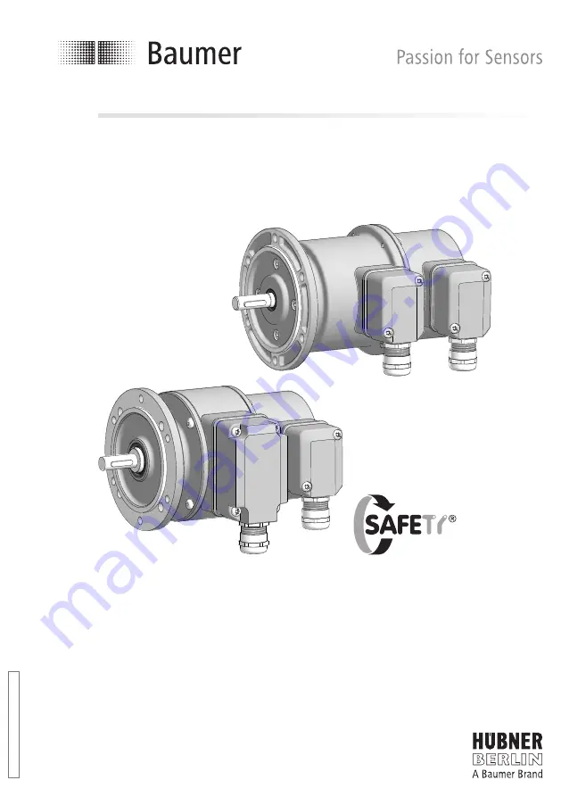
POG 90 + FSL

Kombination

Inkrementaler Drehgeber mit integriertem  

Fliehkraftschalter

Combination

Incremental encoder with integrated  

centrifugal switch

Montage- und Betriebsanleitung

Mounting and operating instructions

M

B1

54

.1 - 1

10

64

67

1

  B

au

m

er

_P

O

G

90

-F

S

L_

II_

D

E

-E

N

 (1

9A

3)

Содержание Baumer FSL

Страница 1: ...aler Drehgeber mit integriertem Fliehkraftschalter Combination Incremental encoder with integrated centrifugal switch Montage und Betriebsanleitung Mounting and operating instructions MB154 1 11064671...

Страница 2: ...n 12 5 1 Kleiner Klemmenkasten 12 6 Elektrischer Anschluss 13 6 1 POG 90 13 6 1 1 Kabelanschluss 13 6 1 1 1 Gro er Klemmenkasten Schritt 1 bis 3 13 6 1 1 2 Gro er Klemmenkasten Schritt 4 und 5 14 6 1...

Страница 3: ...Small terminal box 12 6 Electrical connection 13 6 1 POG 90 13 6 1 1 Cable connection 13 6 1 1 1 Big terminal box Step 1 up to 3 13 6 1 1 2 Big terminal box Step 4 and 5 14 6 1 1 3 Big terminal box S...

Страница 4: ...wischen 20 C bis 85 C am Geh use gemessen 1 7 EU Konformit tserkl rung gem den europ ischen Richtlinien 1 8 Wir gew hren 2 Jahre Gew hrleistung im Rahmen der Bedingungen des Zentralverbandes der Elekt...

Страница 5: ...5 C measured at the housing 1 7 EU Declaration of Conformity meeting to the European Directives 1 8 We grant a 2 year warranty in accordance with the regulations of the ZVEI Central Association of the...

Страница 6: ...enen Abst nde und oder Winkel unbedingt einhalten 2 4 Zerst rungsgefahr durch mechanischen Schock Starke Ersch tterungen z B Hammerschl ge k nnen zur Zerst rung der Abtastung f hren Niemals Gewalt anw...

Страница 7: ...essential that the specified clearances and or angles are observed 2 4 Risk of destruction due to mechanical shock Violent shocks e g due to hammer impacts can lead to the destruction of the sensing s...

Страница 8: ...hlussklemmen FSL siehe Abschnitt 6 2 1 Je nach Version 1 Housing POG 90 2 Housing FSL 3 Solid shaft with key 4 EURO flange B10 5 1 Terminal box cover POG 90 6 1 Torx slotted screw M4x32 mm 7 1 Cable g...

Страница 9: ...tlich siehe Abschnitt 6 1 5 20 Anschlusskabel f r FSL 16 Installation fitting customized 17 Fixing screws M6x16 mm for installation fit ting ISO 4017 18 Spring disk coupling K 35 available as accessor...

Страница 10: ...Winkelfehler f hren kann Rundlauf fehler verursachen Vibrationen die die Lebensdauer des Ger tes verk rzen k nnen The drive shaft should have as less runout as possible because this can otherwise res...

Страница 11: ...e Mounting 4 MB154 1 11064671 Baumer_POG90 FSL_II_DE EN 19A3 8 4 3 Schritt 3 4 4 Schritt 4 4 3 Step 3 4 4 Step 4 Siehe Seite 6 See page 6 Anzugsmoment Tightening torque Mt 1 3 10 Nm 17 4 16 17 2 5 mm...

Страница 12: ...ing Zul ssiger Parallelversatz Admissible parallel misalignment Zul ssiger Winkelfehler Admissible angular error Zul ssige Axialbewegung Admissible axial movement 0 2 0 05 1 Mit isolierender Kunststof...

Страница 13: ...nhalten 5 6 Note when using a jaw type coupling for example ROTEX Incorrect mounting of the jaw type cou pling can damage the device Use a depth gauge to find and observe the correct distances L L1 se...

Страница 14: ...1 4 6 Montagehinweis 4 6 Mounting instruction i Wir empfehlen das Ger t so zu montieren dass der Kabelanschluss keinem direkten Wassereintritt ausgesetzt ist i It is recommended to mount the device wi...

Страница 15: ...610 5 1 Kleiner Klemmenkasten 73656 5 Dimensions 5 1 Big terminal box 74610 5 1 Small terminal box 73656 Positive Drehrichtung Positive rotating direction Positive Drehrichtung Positive rotating direc...

Страница 16: ...verwenden To ensure the specified protection of the device the correct cable diameter must be used 6 Elektrischer Anschluss 6 1 POG 90 6 1 1 Kabelanschluss 6 1 1 1 Gro er Klemmenkasten Schritt 1 bis 3...

Страница 17: ...Abschnitt 6 1 4 1 View X see section 6 1 4 1 8 9 7 19 Siehe Seite 5 oder 6 See page 5 or 6 D SUB Buchse zum Anschluss an das Ger tegeh use siehe Abschnitt 6 1 1 3 D SUB connector female for connectin...

Страница 18: ...nection 6 1 POG 90 6 1 1 Kabelanschluss 6 1 1 3 Gro er Klemmenkasten Schritt 6 6 1 POG 90 6 1 1 Cable connection 6 1 1 3 Big terminal box Step 6 Gro er um 180 wendbarer Klemmenkasten Big terminal box...

Страница 19: ...Kabel durchmesser zu verwenden To ensure the specified protection of the device the correct cable diameter must be used 5 13 mm Um 180 wendbarer Klemmenkasten Terminal box turn by 180 Kabelschirm Cabl...

Страница 20: ...usgangssignal Kanal 1 Output signal channel 1 K1 A A Ausgangssignal Kanal 1 invertiert Output signal channel 1 inverted K2 B B Ausgangssignal Kanal 2 90 versetzt zu Kanal 1 Output signal channel 2 off...

Страница 21: ...s Danger of damage Please beware of possible voltage drop in long cable leads inputs and outputs Do not connect voltage supply to outputs Danger of damage Please beware of possible voltage drop in lon...

Страница 22: ...Es wird empfohlen das Baumer H bner Sensorkabel HEK 8 zu verwenden oder ersatzweise ein geschirmtes paarig ver seiltes Kabel Das Kabel sollte in einem St ck und getrennt von Stromkabeln verlegt werde...

Страница 23: ...ion 6 6 2 FSL 6 2 1 Kabelanschluss 6 2 FSL 6 2 1 Cable connection 14 13 12 20 Ansicht Z siehe Abschnitt 6 2 2 View Z see section 6 2 2 15 Siehe Seite 5 oder 6 See page 5 or 6 5 13 mm Um 180 wendbarer...

Страница 24: ...Terminal assignment 1 2 3 3 4 1 2 4 Schlie er Make contact ffner Break contact Ansicht Z Anschlussklemmen siehe Abschnitt 6 2 1 1 View Connecting terminal see section 6 2 1 1 Ausgangsschaltleistung Ou...

Страница 25: ...ge 7 1 Schritt 1 7 Dismounting 7 1 Step 1 Siehe Seite 5 oder 6 See page 5 or 6 7 2 Schritt 2 7 2 Step 2 18 17 7 3 Schritt 3 7 3 Step 3 18 Vor Demontage des Ger tes alle elektrischen Anschl sse trennen...

Страница 26: ...ro Umdrehung 1024 10000 je nach Bestellung Phasenverschiebung 90 8 Tastverh ltnis 44 56 Referenzsignal Nullimpuls Breite 90 Ausgabefrequenz 250 kHz Ausgangssignale K1 K2 K0 invertierte Ausgangsstufen...

Страница 27: ...je nach Bestellung Betriebsdrehmoment typ 3 Ncm Tr gheitsmoment Rotor 320 gcm2 Werkstoff Geh use Aluminium Druckguss Welle Edelstahl Betriebstemperatur 20 85 C Widerstandsf higkeit IEC 60068 2 6 Vibra...

Страница 28: ...s per revolution 1024 10000 as ordered Phase shift 90 8 Duty cycle 44 56 Reference signal Zero pulse width 90 Output frequency 250 kHz Output signals K1 K2 K0 inverted Output stages HTL TTL RS422 as o...

Страница 29: ...pm s as ordered Operating torque typ 3 Ncm Rotor moment of inertia 320 gcm2 Material Housing aluminium die cast Shaft stainless steel Operating temperature 20 85 C Resistance IEC 60068 2 6 Vibration 5...

Страница 30: ...G 151 HEAG 154 Fiber optic links HEAG 171 HEAG 176 Digital speed switch DS 93 Analyzer for encoders HENQ 1100 9 Zubeh r Federscheibenkupplung K 35 Sensorkabel f r Drehgeber HEK 8 Werkzeugset Bestellnu...

Страница 31: ...MB154 1 11064671 Baumer_POG90 FSL_II_DE EN 19A3...

Страница 32: ...69003 0 Fax 49 0 30 69003 104 info baumerhuebner com www baumer com motion Baumer_POG90 FSL_II_DE EN 19A3 10 12 2019 MB154 1 11064671 Originalsprache der Anleitung ist Deutsch Technische nderungen vo...

Отзывы: