


Installation __________________________________________________________________________
RF-MCGARDPRO
Hubbell Power Systems, Inc.
–
RFL™
Products
July 1, 2022
©2022 Hubbell Incorporated
3-33
3.10
System Boot-Up Sequence
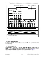
When the LEDs on the front panel display (
) are lit the unit has booted up. This
should take less than 2 minutes. However, for a more detailed description of the boot-up process,
proceed as follows.
With the front panel open do the following:
1.
Verify that a boot up is in progress as displayed by the LEDs (DS1-DS4) on the Controller
Module.
P
S
48
/125
V
Single Main Controller (Slot 2)
Single Power Supply
Normal
Disable
DS-1
DS-2
DS-4
DS-3
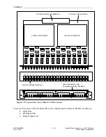
Figure 3-27. Location of LEDs on Controller Board
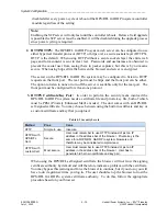
LED
Purpose
unlit
Red
Amber
Green
DS-1
System Status
Flashing Red is
the initial boot
sequence
Booting
continues
Solid green means
the boot Complete
DS-2
Ethernet ports
No
cable
NA
Front port is
connected and
takes priority
Connection through
rear port
DS-3
Redundancy
Control
Not functioning,
switch in disabled
position or On-
board fault
Light toggles
between Amber
and Green while
booting.
Redundancy
control*
DS-4
Logic Bus
Logic error or
failure
NA
Good
* The 3U chassis does not support redundancy, therefore this LED under a normal condition DS-3
in a 3U cabinet should be solid green.
The complete boot-up process will take less than 2 minutes.
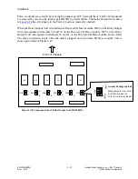
2.
Verify the position of the Toggle Switch SW2. In the 3U chassis, SW2 should be in the
NORM position (left-front view) and not in the Disable position.
After a successful boot up, the HPS/RFL GARD Pro system is ready for interrogation through
the front or rear Ethernet Port.


