Power Line Carrier ____________________________________________________________________
RF-MCGARDPRO
Hubbell Power Systems, Inc.
–
RFL™
Products
July 1, 2022
©2022 Hubbell Incorporated
5-7
5.2
Making Connections to the Rear Analog PLC Module
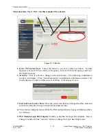
Please refer to the “as supplied drawing” provided with your the HPS/RFL GARD Pro system
for customer specific wiring details, an example is shown below.
Note:
Any field modifications should only be performed by qualified personnel.
Front view of
RFL™ GARD
Pro™ System chassis
Front view of
RFL™ GARD
Pro™ System chassis with
front panel removed
Rear view of
RFL™ GARD
Pro™ System chassis
Jumper Settings
(PLC option)
Input/Output
mapping
System Jumper
Settings
Figure 5-2. As Supplied Drawing
CAUTION
Electro Static Discharge damage
The HPS/RFL GARD Pro system PLC Module set is a Static Sensitive Device. Persons working
on this equipment must observe
E
lectro
S
tatic
D
ischarge (ESD) precautions. As a minimum you
must use anti-static devices such as wrist straps and floor mats and leave modules in their anti-
static bags until they are ready to be installed.
Before proceeding to make connections to the Analog PLC Module, ensure that all the modules
in the chassis are correctly seated:
1)
Remove the front panel to the HPS/RFL GARD Pro system chassis
2)
Using minimal force, remove and re-seat all front panel modules.
Typically, when a single PLC module set is used they are installed in a 3U chassis, however if
more than one PLC is required a 6U chassis is needed. Depending on the configuration and
power consumption limits a second power supply may be required. Details on external
connections to a second power supply are shown in
Module as it would appear in the rear of a 3U chassis.


