


Power Line Carrier ____________________________________________________________________
RF-MCGARDPRO
Hubbell Power Systems, Inc.
–
RFL™
Products
July 1, 2022
©2022 Hubbell Incorporated
5-1
Power Line Carrier
5.1
Power Line Carrier Function
The HPS/RFL™ GARD Pro™ system with Power Line Carrier (PLC) is a Single Function PLC
protection unit. The PLC function consists of two plug-in modules: A digital module which
plugs into the front of the chassis, and an Analog module which plugs into the rear of the chassis.
Both modules can be installed in a 3U or 6U the HPS/RFL GARD Pro system chassis.
The single function channel can be configured for two modes of operation: FSK (Frequency
Shift Key), or On/Off. In FSK mode, it can be configured to support either 2F or 3F operation.
In On/Off mode, it can be configured to support both Normal Checkback and Hard Carrier
Checkback.
In addition to performing the normal PLC functions, the unit will monitor the transmit interface
to measure transmit power, reflected power, trans-hybrid loss, and receive signal strength.
5.1.1 FSK Operation
As stated above the HPS/RFL GARD Pro system with PLC supports two FSK operational
modes: 2F and 3F.
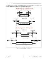
In 2F operation a guard tone is located at a fixed deviation below or above the channel center
frequency. At the occurrence of a trip, the tone shifts to the opposite side of the channel center
frequency.
In 3F operation a guard tone is located at the channel center frequency. One of two following
trips can occur causing the tone to shift a fixed deviation:
1.
below
the channel center frequency
2.
above
the channel center frequency
The performance of 2F and 3F operation is defined by the Maximum Trip Transport Delay,
Dependability and Security.
-
Maximum Trip Transport Delay:
The time between the following two events:
1)
When the unit transmitter is notified of a trip event through the Logic Bus, until
2)
The unit receiver on the other side of the link writes the trip event into the Logic Bus
status registers.
More specifically, it is defined as the delay between the Logic Bus frame reception
interrupt which contains the trip event information until the status register is written in
the receiver. The Maximum Trip Transport Delay is defined by the three operational
configurations for the following:
o
o
Minimum Channel Spacing (FSK).
-
Dependability:
The probability that a trip event will be successfully communicated to
the other end of the link within the Maximum Trip Transport Delay as a function of the
signal to noise ratio of the link.