background image

2    Introduction 

Tecal RH5485 Server   

Problem Determination and Service Guide 


2-8 

Huawei Proprietary and Confidential           

Copyright © Huawei Technologies Co., Ltd. 


Issue  02  (2011-05-25) 


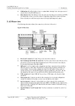
2.4.3 Rear view LEDs 

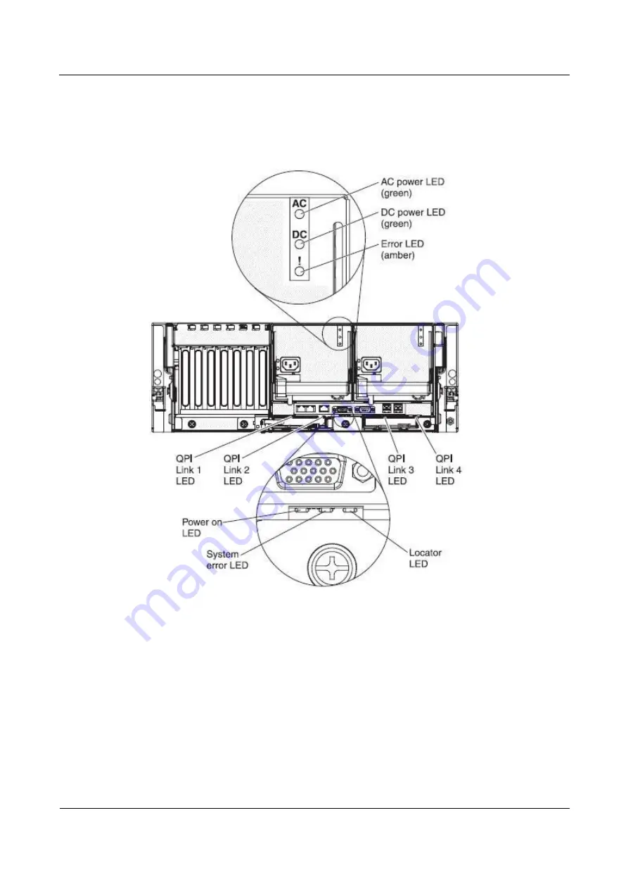
The following illustration shows the LEDs on the rear of the server. 

Figure 2-6


Rear view LEDs 


AC power LED: 

Each hot-swap power supply has an ac power LED and a dc power 

LED. When the ac power LED is lit, it indicates that sufficient power is coming into the 
power supply through the power cord. During typical operation, both the ac and dc 
power LEDs are lit. 


DC power LED: 

Each hot-swap power supply has a dc power LED and an ac power 

LED. When the dc power LED is lit, it indicates that the power supply is supplying 
sufficient dc power to the system. During typical operation, both the ac and dc power 
LEDs are lit. 


Error LED: 

When the power-supply error LED is lit, it indicates a problem with the 

power supply. 


QPI Link LEDs 1 - 4: 

When the QuickPath Interconnect (QPI) link LEDs are lit, they 

indicate that the QPI links are fully established. 

Содержание Tecal RH5485

Страница 1: ...Tecal RH5485 Server V100R001C00 Problem Determination and Service Guide Issue 02 Date 2011 05 25 HUAWEI TECHNOLOGIES CO LTD ...

Страница 2: ......

Страница 3: ... customer All or part of the products services and features described in this document may not be within the purchase scope or the usage scope Unless otherwise specified in the contract all statements information and recommendations in this document are provided AS IS without warranties guarantees or representations of any kind either express or implied The information in this document is subject ...

Страница 4: ......

Страница 5: ...tions The symbols that may be found in this document are defined as follows Symbol Description Indicates a hazard with a high level of risk which if not avoided will result in death or serious injury Indicates a hazard with a medium or low level of risk which if not avoided could result in minor or moderate injury Indicates a potentially hazardous situation which if not avoided could result in equ...

Страница 6: ... History Updates between document issues are cumulative Therefore the latest document issue contains all updates made in previous issues Changes in Issue 02 2011 05 25 This issue is the second official release which incorporates the following changes Some figures in chapter 2 are updated Some tables in chapter 3 are updated Changes in Issue 01 2010 08 30 Initial field trial release ...

Страница 7: ... 2 8 2 5 Internal LEDs connectors and jumpers 2 12 2 5 1 Memory card DIMM connectors 2 12 2 5 2 Memory card LEDs and button 2 12 2 5 3 Memory card connectors on the microprocessor board 2 14 2 5 4 Microprocessor board connectors 2 14 2 5 5 Microprocessor board LEDs 2 15 2 5 6 I O board connectors 2 17 2 5 7 I O board LEDs 2 17 2 5 8 I O board jumpers 2 18 2 5 9 SAS backplane connectors 2 20 3 Diag...

Страница 8: ...utton 3 52 3 7 Power supply LEDs 3 61 3 8 Recovering the server firmware 3 63 3 8 1 In band automatic recovery method 3 63 3 8 2 In band manual recovery method 3 64 3 8 3 Out of band method 3 64 3 9 Three boot failure 3 64 3 10 System event log 3 65 3 11 Integrated management module error messages 3 65 3 12 Solving Ethernet controller problems 3 102 3 13 Solving undetermined problems 3 103 3 14 Pr...

Страница 9: ...ted management module 6 10 6 2 7 Obtaining the IP address for the Web interface access 6 12 6 2 8 Logging on to the Web interface 6 12 6 2 9 Using the embedded hypervisor 6 13 6 2 10 Using the remote presence capability and blue screen capture 6 14 6 2 11 Enabling the Broadcom Gigabit Ethernet Utility program 6 14 6 2 12 Configuring the Broadcom Gigabit Ethernet controller 6 15 6 2 13 Configuring ...

Страница 10: ......

Страница 11: ...2 9 Memory card LEDs and button 2 13 Figure 2 10 Memory card connectors 2 14 Figure 2 11 Microprocessor board connectors 2 15 Figure 2 12 Microprocessor board LEDs 2 16 Figure 2 13 I O board connectors 2 17 Figure 2 14 I O board LEDs 2 18 Figure 2 15 I O board jumpers 2 19 Figure 2 16 SAS backplane connectors 2 20 Figure 3 1 The operator information panel 3 49 Figure 3 2 Lit LEDs 3 49 Figure 3 3 L...

Страница 12: ......

Страница 13: ...bedded hypervisor problems 3 34 Table 3 5 General problems 3 34 Table 3 6 Hard disk drive problems 3 35 Table 3 7 Intermittent problems 3 36 Table 3 8 USB keyboard mouse or pointing device problems 3 37 Table 3 9 Memory problems 3 38 Table 3 10 Microprocessor problems 3 39 Table 3 11 Monitor or video problems 3 40 Table 3 12 Optional device problems 3 42 Table 3 13 Power problems 3 43 Table 3 14 S...

Страница 14: ... 05 25 Table 4 1 Parts listing RH5485 4 3 Table 4 2 Consumable parts 4 6 Table 5 1 Low cost and low power DIMM installation sequence 5 30 Table 5 2 Low cost and low power memory card installation sequence 5 30 Table 5 3 High performance memory card installation sequence 5 30 Table 5 4 Memory card installation sequence for memory mirroring configuration 5 31 ...

Страница 15: ...ose a problem with your server 1 Determine what has changed Determine whether any of the following items were added removed replaced or updated before the problem occurred Hardware components Device drivers and firmware System software Server Firmware System input power or network connections If possible return the server to the condition it was in before the problem occurred 2 View the light path...

Страница 16: ...g the firmware 4 Check for and correct an incorrect configuration If the server is incorrectly configured a system function can fail to work when you enable it if you make an incorrect change to the server configuration a system function that has been enabled can stop working a Make sure that all installed hardware and software are supported b Make sure that the server operating system and softwar...

Страница 17: ... remains contact HUAWEI or an approved warranty service provider for assistance with additional problem determination and possible hardware replacement 1 2 Undocumented problems If you have completed the diagnostic procedure and the problem remains the problem might not have been previously identified by HUAWEI After you have verified that all code is at the latest level all hardware and software ...

Страница 18: ......

Страница 19: ...est without a service contract you will be charged for the installation Tier 2 customer replaceable unit You may install a Tier 2 CRU yourself or request HUAWEI to install it at no additional charge under the type of warranty service that is designated for your server Field replaceable unit FRU FRUs must be installed only by trained service technicians 2 1 Related documentation In addition to this...

Страница 20: ...attention notice is placed just before the instruction or situation in which damage might occur Caution These statements indicate situations that can be potentially hazardous to you A caution statement is placed just before the description of a potentially hazardous procedure step or situation Danger These statements indicate situations that can be potentially lethal or extremely hazardous to you ...

Страница 21: ... Proprietary and Confidential Copyright Huawei Technologies Co Ltd 2 3 Table 2 1 Features and specifications 2 4 Server controls connectors LEDs and power This section describes the controls light emitting diodes LEDs connectors on the front and rear of the server and how to turn the server on and off ...

Страница 22: ...use USB 1 and 2 connectors Connect USB devices to these connectors Scalability LED This LED is lit and remains on during POST on the primary server when the UEFI and the IMM detect more than four microprocessors This LED is lit and remains on after POST on the secondary server Hard disk drive activity LED When this LED is flashing it indicates that the drive is in use Hard disk drive status LED On...

Страница 23: ... the IMM Web interface see Logging on to the Web interface Ethernet icon LED This LED lights the Ethernet icon Information LED When this LED is lit it indicates that a noncritical event has occurred An LED on the light path diagnostics panel is also lit to help isolate the error System error LED When this LED is lit it indicates that a system error has occurred An LED on the light path diagnostics...

Страница 24: ...ed do not run the server for more than 10 minutes while the light path diagnostics panel is pulled out of the server 2 Light path diagnostics LEDs remain lit only while the server is connected to power Figure 2 4 Checkpoint code display Remind button This button places the system error LED on the front panel into Remind mode In Remind mode the system error LED flashes once every 2 seconds until th...

Страница 25: ... is used only by the integrated management module IMM QPI ports 1 4 In a single node configuration use these connectors to insert either a QPI wrap card or a filler panel The QPI wrap cards enable increased performance in certain models In a two node configuration insert the QPI cables in these ports to connect another server or a MAX5 memory expansion module to your server See the documentation t...

Страница 26: ...at sufficient power is coming into the power supply through the power cord During typical operation both the ac and dc power LEDs are lit DC power LED Each hot swap power supply has a dc power LED and an ac power LED When the dc power LED is lit it indicates that the power supply is supplying sufficient dc power to the system During typical operation both the ac and dc power LEDs are lit Error LED...

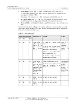
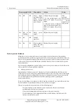
Страница 27: ...ower supply LEDs and the power on LED on the operator information panel and suggested actions to correct the detected problems Figure 2 7 Power supply LEDs Power supply LEDs Description Action Notes AC DC Error Off Off Off No ac power to either power supply or a problem with the ac power source 1 Check the ac power to the server 2 Make sure that the power cord is connected to a functioning power s...

Страница 28: ...such as a remote request to turn on the server The power on LED flashes to indicate that the server is connected to ac power but not turned on In a two node configuration connect both servers to an ac power source as close to the same time as possible to ensure optimum operation Turning on the server Approximately 5 minutes or up to 8 minutes in a 2 node configuration after the server is connected...

Страница 29: ...source Some operating systems require an orderly shutdown before you turn off the server See your operating system documentation for information about shutting down the operating system Statement 5 WARNING The power control button on the device and the power switch on the power supply do not turn off the electrical current supplied to the device The device also might have more than one power cord ...

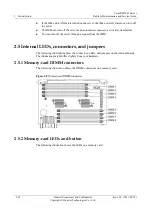
Страница 30: ...esponse to a critical system failure You can turn off the server through a request from the IMM 2 5 Internal LEDs connectors and jumpers The following illustrations show the connectors LEDs and jumpers on the internal boards The illustrations might differ slightly from your hardware 2 5 1 Memory card DIMM connectors The following illustration shows the DIMM connectors on a memory card Figure 2 8 M...

Страница 31: ...harged and is able to light other LEDs Light path diagnostics button Push this button to relight the error LED that had previously been lit Memory card DIMM error LED When this LED is lit it indicates that an error has occurred in one of the DIMMs on the memory card or that there is a problem with the memory card Memory card only error LED When this LED is lit it indicates that an error has occurr...

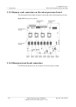
Страница 32: ... Technologies Co Ltd Issue 02 2011 05 25 2 5 3 Memory card connectors on the microprocessor board The following illustration shows the memory card connectors on the microprocessor board Figure 2 10 Memory card connectors 2 5 4 Microprocessor board connectors The following illustration shows the connectors on the microprocessor board ...

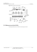
Страница 33: ...e 2 Introduction Issue 02 2011 05 25 Huawei Proprietary and Confidential Copyright Huawei Technologies Co Ltd 2 15 Figure 2 11 Microprocessor board connectors 2 5 5 Microprocessor board LEDs The following illustration shows the LEDs on the microprocessor board ...

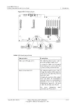
Страница 34: ...sor board non light path diagnostics status LEDs LED Description System management heartbeat LED When this LED is flashing at a constant rate of once every 2 seconds it indicates normal operation of the IMM Note If this LED is not lit it indicates that the microprocessor board must be reseated or replaced trained service technician only see Removing the microprocessor board assembly and Replacing ...

Страница 35: ...rocessor Note You must remove the top cover bracket before you can see these LEDs Microprocessor board error LED When this LED is lit it indicates that an error has occurred on the microprocessor board Note You must remove the memory card or memory filler in memory card connector 7 before you can see this LED 2 5 6 I O board connectors The following illustration shows the connectors on the I O boa...

Страница 36: ...ight path diagnostics status LEDs LED Description Slots 1 7 error LEDs When one of these LEDs is lit it indicates that an error has occurred in the associated I O slot I O board error LED When this LED is lit it indicates that an error has occurred on the I O board Note You must look at the server at an angle from the front to see this LED 2 5 8 I O board jumpers The following illustration shows t...

Страница 37: ...he jumper to pins 2 and 3 to prevent a Wake on LAN packet from waking the system when the system is in the powered off state Password override J29 The default position is pins 1 and 2 Change the position of this jumper to pins 2 and 3 to bypass the power on password check Changing the position of this jumper does not affect the administrator password check if an administrator password is set If yo...

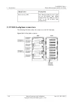
Страница 38: ...Ltd Issue 02 2011 05 25 Jumper name Description Boot recovery J22 The default position is pins 1 and 2 to use the primary page during startup Move the jumper to pins 2 and 3 to use the secondary page during startup 2 5 9 SAS backplane connectors The following illustration shows the connectors on the SAS backplane Figure 2 16 SAS backplane connectors ...

Страница 39: ...set Checkpoint codes are shown on the checkpoint display which is on the light path diagnostics panel 3 2 Event logs Error codes and messages are displayed in the following types of event logs POST event log This log contains the three most recent error codes and messages that were generated during POST You can view the POST event log from the Setup utility System event log This log contains POST ...

Страница 40: ... Select System Event Logs and use one of the following procedures To view the POST event log select POST Event Viewer To view the system event log select System Event Log 3 2 2 Viewing event logs without restarting the server If the server is not hung methods are available for you to view one or more event logs without having to restart the server If IPMItool is installed in the server you can use...

Страница 41: ...ts a problem an error message is sent to the POST event log The following table describes the POST error codes and suggested actions to correct the detected problems These errors can appear as severe warning or informational Table 3 2 POST error codes Follow the suggested actions in the order in which they are listed in the Action column until the problem is solved See Table Parts Listing to deter...

Страница 42: ...ating the firmware 2 Trained service technician only Remove and replace the affected microprocessor error LED is lit with a supported type Microprocessor mismatch 1 Run the Setup utility and view the microprocessor information to compare the installed microprocessor specifications 2 Trained service technician only Remove and replace one of the microprocessors so that they both match 0011004 Microp...

Страница 43: ... the DIMMs match and are installed in the correct sequence see Memory cards and memory modules DIMM 0051009 No memory detected 1 Make sure that the server contains DIMMs 2 Reseat the memory cards 3 Reseat the DIMMs 4 Install the memory cards and DIMMs in the correct sequence see Memory cards and memory modules DIMM 005100A No usable memory detected 1 Make sure that the server contains DIMMs 2 Rese...

Страница 44: ...e DIMMs and then restart the server 2 Replace the following components one at a time in the order shown restarting the server each time a DIMMs b Memory card 00580A1 Invalid DIMM population for mirroring mode 1 If a fault LED is lit resolve the failure 2 Install the memory cards and DIMMs in the correct sequence see Memory cards and memory modules DIMM 00580A4 Memory population changed Information...

Страница 45: ...ters 3 Update the PCI device firmware 4 Remove the adapters from the I O board 5 Replace the following components one at a time in the order shown restarting the server each time a The adapters b Trained service technician only The I O board shuttle 2018002 Option ROM resource allocation failure Informational message that some devices might not be initialized 1 If possible rearrange the order of t...

Страница 46: ...ver firmware image because of ABR 1 Run the Setup utility select Load Default Settings and save the settings to recover the primary server firmware settings 2 Turn off the server and remove it from the power source 3 Reconnect the server to the power source and then turn on the server 305000A RTC date time is incorrect 1 Adjust the date and time settings in the Setup utility and then restart the s...

Страница 47: ...nd then restart the server 3108007 System configuration restored to default settings Information only This is message is usually associated with the CMOS battery clear event 3138002 Boot configuration error 1 Remove any recent configuration changes that you made in the Setup utility 2 Run the Setup utility select Load Default Settings and save the settings 3808000 Error updating system configurati...

Страница 48: ...he microprocessor board 3818004 Core Root of Trust Measurement CRTM system error 1 Run the Setup utility select Load Default Settings and save the settings 2 Trained service technician only Replace the microprocessor board 3818005 Current Bank Core Root of Trust Measurement CRTM capsule signature invalid 1 Run the Setup utility select Load Default Settings and save the settings 2 Trained service t...

Страница 49: ...re you run the diagnostic programs you must determine whether the failing server is part of a shared hard disk drive cluster two or more servers sharing external storage devices If it is part of a cluster you can run all diagnostic programs except the ones that test the storage unit that is a hard disk drive in the storage unit or the storage adapter that is attached to the storage unit The failin...

Страница 50: ... all external devices 3 Check all internal and external devices for compatibility 4 Check all cables and power cords 5 Set all monitor controls to the middle positions 6 Turn on all external devices 7 Turn on the server If the server does not start see Troubleshooting tables 8 Check the system error LED on the operator information panel If it is flashing check the light path diagnostics LEDs see L...

Страница 51: ...the CD or DVD drive is attached primary or secondary is enabled in the Setup utility The signal cable and connector are not damaged and the connector pins arenot bent All cables and jumpers are installed correctly The correct device driver is installed for the CD or DVD drive 2 Run the CD or DVD drive diagnostic programs 3 Reseat the following components a CD or DVD drive see Removing the DVD driv...

Страница 52: ...Boot Device 2 If the embedded hypervisor is on an internal flash memory device make sure that the internal flash memory device is seated in the connector correctly see Removing the internal flash memory and Replacing the internal flash memory 3 See the documentation that comes with the embedded hypervisor for setup and configuration information 4 Make sure that other software works on the server 3...

Страница 53: ... that is indicated then run the hard disk drive diagnostic test again If the remaining drives are recognized replace the drive that you removed with a new one The server stops responding during the hard disk drive diagnostic test Remove the hard disk drive that was being tested when the server stopped responding see Removing a hot swap hard disk drive and run the diagnostic test again If the hard ...

Страница 54: ...laceable units CRU and which components are field replaceable units FRU If an action step is preceded by Trained service technician only that step must be performed only by a trained service technician Symptom Action A problem occurs only occasionally and is difficult to diagnose 1 Make sure that All cables and cords are connected securely to the rear of the server and attached devices When the se...

Страница 55: ... error message 301 from being displayed during startup 2 Make sure that The keyboard cable is securely connected The server and the monitor are turned on 3 Reseat the following components a Keyboard b I O board assembly see Removing the I O board shuttle and Replacing the I O board shuttle 4 Replace the components listed in step 3 one at a time in the order shown restarting the server each time Th...

Страница 56: ...discrepancy Note Each node in a multi node configuration uses 256 MB of system memory In a two node configuration make sure that both nodes have started and all the devices between the two nodes have been counted The memory modules are seated correctly see Removing a DIMM and Replacing a DIMM You have installed the correct type of memory If you changed the memory you updated the memory configurati...

Страница 57: ... diagnostics LEDs see Light path diagnostics 2 Make sure that the server supports all the microprocessors and that the microprocessors match in speed and cache size 3 Reseat the following components a Microprocessor 1 see Removing a microprocessor and heat sink b Trained service technician only Microprocessor board see Removing the microprocessor board assembly and Replacing the microprocessor boa...

Страница 58: ...rams the problem might be a video device driver 5 Replace the I O board shuttle The screen is blank 1 If the server is attached to a KVM switch bypass the KVM switch to eliminate it as a possible cause of the problem connect the monitor cable directly to the correct connector on the rear of the server 2 Make sure that The server is turned on If there is no power to the server see Power problems Th...

Страница 59: ...fields around other devices such as transformers appliances fluorescent lights and other monitors can cause screen jitter or wavy unreadable rolling or distorted screen images If this happens turn off the monitor Attention Moving a color monitor while it is turned on might cause screen discoloration Move the device and the monitor at least 305 mm 12 in apart and turn on the monitor Notes a To prev...

Страница 60: ...tallation instructions that came with the device and the device is installed correctly You have not loosened any other installed devices or cables You updated the configuration information in the Setup utility Whenever memory or any other device is changed you must update the configuration 2 Reseat the device that you just installed 3 Replace the device that you just installed An HUAWEI optional d...

Страница 61: ...te The power control button will not function for up to 3 minutes after the server has been connected to ac power 1 Make sure that the operator information panel power control button is working correctly a Disconnect the ac power cord for 20 seconds then reconnect the ac power cord and restart the server b Reseat the operator information panel cables and then repeat step 1a If the server starts re...

Страница 62: ...rmine whether you are using an Advanced Configuration and Power Management ACPI or a non ACPI operating system If you are using a non ACPI operating system complete the following steps a Press Ctrl Alt Delete b Turn off the server by holding the power control button for 5 seconds c Restart the server d If the server fails POST and the power control button does not work disconnect the ac power cord...

Страница 63: ...ified by the operating system is less than the number of installed serial ports 1 Make sure that Each port is assigned a unique address in the Setup utility and none of the serial ports is disabled The serial port adapter if one is present is seated correctly 2 Reseat the serial port adapter see Removing an adapter and Replacing an adapter 3 Replace the serial port adapter A serial device does not...

Страница 64: ...hat the server supports the ServerGuide program and has a startable bootable CD or DVD drive 2 If the startup boot sequence settings have been changed make sure that the CD or DVD drive is first in the startup sequence 3 If more than one CD or DVD drive is installed make sure that only one drive is set as the primary drive Start the CD from the primary drive The operating system installation progr...

Страница 65: ... must be performed only by a trained service technician Symptom Action You suspect a software problem 1 To determine whether the problem is caused by the software make sure that The server has the minimum memory that is needed to use the software For memory requirements see the information that comes with the software If you have just installed an adapter the server might have an adapter address c...

Страница 66: ...lems See Monitor or video problems 3 6 Light path diagnostics Light path diagnostics is a system of LEDs on various external and internal components of the server When an error occurs LEDs are lit throughout the server By viewing the LEDs in a particular order you can often identify the source of the error The server is designed so that LEDs remain lit when the server is connected to an ac power s...

Страница 67: ...tep 2 The following illustration shows the operator information panel Figure 3 1 The operator information panel 2 To view the light path diagnostics panel press the release latch on the front of the operator information panel to the left then slide it forward This reveals the light path diagnostics panel Lit LEDs on this panel indicate the type of error that has occurred Figure 3 2 Lit LEDs NOTE T...

Страница 68: ...problem For example a microprocessor error will light the LED next to the failing microprocessor on the microprocessor board The following illustration shows the LEDs on the microprocessor board Figure 3 3 LEDs on the microprocessor board NOTE a You must remove the memory card or memory card filler from memory card connector 7 before you can see the microprocessor board error LED b You must remove...

Страница 69: ...ermination and Service Guide 3 Diagnostics Issue 02 2011 05 25 Huawei Proprietary and Confidential Copyright Huawei Technologies Co Ltd 3 51 Figure 3 4 LEDs on a memory card The following illustration shows the LEDs on the I O board ...

Страница 70: ...stem error LED flashes while it is in Remind mode and stays in Remind mode until one of the following conditions occurs All known errors or suboptimal conditions are corrected The server is powered back on A new error or suboptimal condition occurs causing the system error LED to be lit again You can also use the remind button to turn off the LOG LED on the light path diagnostics panel and the inf...

Страница 71: ...re off only the power LED is lit or flashing A USB device does not work No action is necessary All LEDs are off the power LED is lit or flashing and the system error LED is lit A machine check has occurred The server is identifying the machine check the server was interrupted while identifying the machine check or the server was unable to identify the machine check 1 Wait several minutes for the s...

Страница 72: ...log if necessary and clear it LINK There is a fault in a QPI port or the QPI scalability cables Notes 1 This LED remains lit until the problem is solved and the server is turned off and restarted 2 If a fault occurs the SMP Expansion Port link LED on the failed port is off 1 If you have a MAX5 attached to the server check to see if the front LINK error LED is lit on the MAX5 or the server Dependin...

Страница 73: ...LED is lit on the MAX5 or the server Depending on which LED is lit will determine which device you need to troubleshoot 2 Reinstall the removed power supply see Replacing the hot swap power supply 3 Check the individual power supply LEDs to find the failing power supply see Rear view LEDs 4 Reseat the failing power supply see Removing a hot swap power supply and Replacing the hot swap power supply...

Страница 74: ... you need to troubleshoot 2 Reinstall the removed fan see Replacing the front hot swap fans 3 If an individual fan LED is lit replace the fan Note A failing fan might not cause the fan LED to be lit 4 Trained service technician only Reseat the microprocessor board see Removing the microprocessor board assembly and Replacing the microprocessor board assembly 5 Trained service technician only Replac...

Страница 75: ...card then press the light path diagnostics button on the memory card to identify the failed card or DIMM see Remind button 3 Reseat the DIMM with the lit LED see Removing a DIMM and Replacing a DIMM 4 Swap the failed DIMM with a known good DIMM or move the failed DIMM to another connector to see whether the error follows the DIMM or stays with the connector Restart the server 5 Replace the followi...

Страница 76: ...oubleshoot 2 Find the failing or missing component by checking the other light path diagnostic LEDs on the operator information panel Make sure the microprocessors match each other speed cache etc 3 Make sure that the fans power supplies microprocessors and memory cards are installed in the correct sequence CPU A microprocessor has failed is missing or has been incorrectly installed 1 If the CNFG ...

Страница 77: ...essor b Trained service technician only Microprocessor board VRM Reserved DASD A hard disk drive has failed or has been removed Note The error LED on the failing hard disk drive is also lit 1 Reinstall the removed drive 2 Reseat the following components a Failing hard disk drive see Removing a hot swap hard disk drive and Replacing a hot swap hard disk drive b SAS hard disk drive backplane see Rem...

Страница 78: ...ot swap hard disk drive d I O board assembly see Removing the I O board shuttle and Replacing the I O board shuttle 3 Replace the components in step 2 one at a time in the order shown restarting the server each time BOARD The I O board shuttle or microprocessor board has failed 1 Find the failing board by checking the LEDs on the I O board shuttle and microprocessor board 2 If the I O board LED is...

Страница 79: ...d for the server to start I O board Power supply Power cord Microprocessor board One microprocessor Two DIMMs on one memory card Operator information panel If the a MAX5 is connected to the server two 2 GB DIMMs on the MAX5 memory expansion module The following illustration shows the locations of the power supply LEDs Figure 3 6 the locations of the power supply LEDs The following table describes ...

Страница 80: ... LED Description Action AC DC Error Off Off Off Off No ac power to the server or a problem with the ac power source 1 Check the ac power to the server 2 Make sure that the power cord is connected to a functioning power source 3 Make sure that the power cord is fully seated in the power supply inlet Lit Off Off Off DC source power problem or system error 1 Reseat one power supply at a time see Remo...

Страница 81: ...are image in the backup bank If the server firmware in the primary bank has become corrupted such as from a power failure during an update you can recover the server firmware in either of two ways In band method Through the automatic boot recovery function automatic or using the boot recovery jumper and an HUAWEI Flash UEFI Update manual Out of band method Using the IMM Web interface and an HUAWEI...

Страница 82: ...adme file 9 Copy the downloaded firmware update package into a directory 10 From a command line type filename s where filename is the name of the executable file that you downloaded with the firmware update package 11 Turn off the server and disconnect all power cords and external cables and then remove the server cover 12 Move the boot recovery jumper back to the primary position pins 1 and 2 13 ...

Страница 83: ...low the suggested actions in the order in which they are listed in the Action column until the problem is solved See Chapter 4 Parts listing RH5485 to determine which components are customer replaceable units CRU and which components are field replaceable units FRU If an action step is preceded by Trained service technician only that step must be performed only by a trained service technician Tabl...

Страница 84: ...nar 3 3V going high upper critical as deasserted Info An upper critical sensor going high has deasserted No action information only Numeric sensor Planar 5V going low lower critical has asserted Error A lower critical sensor going low has asserted Trained service technician only Replace the I O board shuttle Numeric sensor Planar 5V going high upper critical has asserted Error An upper critical se...

Страница 85: ...ical has deasserted Info A lower critical sensor going low has deasserted No action information only Numeric sensor FannTach n fan number Error A lower critical sensor going low has deasserted 1 Reseat the failing fan x which is indicated by the lit LED near the fan connector on the microprocessor board 2 Replace the failing fan x fan number Numeric sensor Fan nA Tach going low lower critical has ...

Страница 86: ...l adapters and standard devices such as Ethernet SCSI and SAS Important Some cluster solutions require specific code levels or coordinated code updates If the device is part of a cluster solution verify that the latest level of code is supported for the cluster solution before you update the code 2 Trained service technician only Replace microprocessor n n microprocessor number An Over Temperature...

Страница 87: ...est level of code is supported for the cluster solution before you update the code 2 Make sure that the installed microprocessors are compatible with each other see Microprocessor for information about microprocessor requirements 3 Trained service technician only Reseat microprocessor n 4 Trained service technician only Replace microprocessor n n microprocessor number Processor n has recovered fro...

Страница 88: ...you update the code 2 Make sure that the installed microprocessors are compatible with each other see Microprocessor for information about microprocessor requirements 3 Trained service technician only Reseat microprocessor n 4 Trained service technician only Replace microprocessor n n microprocessor number Sensor CPU n OverTemp has transitioned to critical from a less severe state n microprocessor...

Страница 89: ...to critical from a non recoverable state n microprocessor number Error A sensor has changed to Critical state from Nonrecoverable state 1 Make sure that the fans are operating that there are no obstructions to the airflow that the air baffles are in place and correctly installed and that the server cover is installed and completely closed 2 Make sure that the heat sink for microprocessor n is inst...

Страница 90: ...tName Error A bus timeout has occurred 1 Remove the adapter from the PCI slot that is indicated by a lit LED 2 Replace the adapter 3 Remove all PCI adapters 4 Trained service technicians only Replace the I O board A software NMI has occurred on sys tem 1 1 CIM_ComputerSystem ElementName Error A software NMI has occurred 1 Check the device driver 2 Reinstall the device driver The System 1 encounter...

Страница 91: ...level of code is supported for the cluster solution before you update the code 2 Trained service technician only Replace the microprocessor board A Uncorrectable Bus Error has occurred on system 1 1 CIM_ComputerSystem ElementName Error A bus uncorrectable error has occurred Sensor Critical Int PCI 1 Check the system event log 2 Check the PCI error LEDs 3 Remove the adapter from the indicated PCI s...

Страница 92: ...t level of code is supported for the cluster solution before you update the code 5 Make sure that all of the installed microprocessors are matching 6 Trained service technician only Replace the microprocessor board A Uncorrectable Bus Error has occurred on system 1 1 CIM_ComputerSystem ElementName Error A bus uncorrectable error has occurred Sensor Critical Int DIMM 1 Check the system event log 2 ...

Страница 93: ...ian only Replace the I O board Power Messages Redundancy Lost for Power Group 1 has asserted Error One power supply has lost AC Power is no longer redundant Install another power supply to acquire redundancy Redundancy Power Group 1 has been restored Info Redundancy has been restored No action information only Failure predicted on EPOW Fault Error AC power lost to a power supply Make sure there is...

Страница 94: ...erable state 1 Turn off the server and disconnect it from power 2 Trained service technician only Remove the microprocessor from socket 1 Note The server will not start when no microprocessor is installed in socket 1 3 Reinstall the microprocessor in socket 1 and restart the server 4 Trained service technician only Replace the failing microprocessor 5 Trained service technician only Replace the mi...

Страница 95: ...ail D Fault has transitioned to non recoverable Error A sensor has changed to Nonrecoverable state 1 Turn off the server and disconnect it from power 2 Trained service technician only Remove the microprocessor from socket 4 Note The server will not start when no microprocessor is installed in socket 1 3 Reinstall the microprocessor in socket 4 and restart the server 4 Trained service technician on...

Страница 96: ...isconnect it from power 2 Remove the adapters from the PCI Express connectors 3 Reinstall each device one at a time starting the server each time to isolate the failing device 4 Replace the failing adapter 5 Trained service technician only Replace the I O board shuttle Sensor P wr Rail H Fault has transitioned to non recoverable Error A sensor has changed to Nonrecoverable state 1 Remove any cable...

Страница 97: ...l state from a normal state 1 Check the OVER SPEC LED see the information about the OVER SPEC LED in Light path diagnostics LEDs 2 Remove the power supplies 3 Replace power supply n 4 Trained service technician only Replace the I O board shuttle n power supply number Sensor PS n 12V OC Fault has transitioned to non critical from a nor mal state n power supply number Warning A sensor has changed to...

Страница 98: ...ans 2 and 3 are not damaged 2 Make sure that the fan connectors 2 and 3 on the microprocessor board are not damaged 3 Make sure that the fans are correctly installed 4 Reseat the fans 5 Replace the fans Redundancy lot for Cooling Zone 3 has asserted Error Redundancy has been lost and is insufficient to continue operation 1 Make sure that the connector on fan 3 is not damaged 2 Make sure that the f...

Страница 99: ...errupt system operation 1 Make sure that the connector on fan 3 is not damaged 2 Make sure that fan connector 3 on the microprocessor board is not damaged 3 Make sure that the fan is correctly installed 4 Reseat the fan 5 Replace the fans The Drive n Status has been removed from unit chassis 1 n hard disk drive number Error A drive has been removed Reseat hard disk drive n n hard disk drive number...

Страница 100: ...ory Errors NOTE A DIMM error message indicates the DIMM but not the memory card on which the error has occurred DIMMs 1 8 are on memory card 1 DIMMs 9 16 are on memory card 2 and so on Memory Expansion Unit 1 was detected as absent Info The memory expansion unit was detected as absent when it was expected to be present Check the QPI cable connections then reboot the server to see if it recovers Me...

Страница 101: ...before you update the code 2 Reseat the DIMMs and run the memory test This test might take up to 30 minutes to run 3 Replace any DIMM that is indicated by a lit error LED Configuration error all DIMMs on subsystem System Memory Error A DIMM configuration error has occurred Make sure that DIMMs are installed in the correct sequence and have the same size type speed and technology Uncorrectable erro...

Страница 102: ...he code 2 Reseat the DIMMs and run the memory test This test might take up to 30 minutes to run 3 Replace any DIMM that is indicated by a lit error LED Configuration error for one of the DIMMs on subsystem System Memory Error A DIMM configuration error has occurred Make sure that DIMMs are installed in the correct sequence and have the same size type speed and technology Uncorrectable error detect...

Страница 103: ...ory cards 4 Run the memory test This test might take up to 30 minutes to run 5 Trained service technician only Replace the microprocessor card Memory Logging Limit Reached for memory device n on subsystem Sys tem Memory n DIMM number Error The memory logging limit has been reached 1 Update the server firmware to the latest level Important Some cluster solutions require specific code levels or coor...

Страница 104: ...ice n on subsystem System Memory n DIMM number Error A DIMM configuration error has occurred Make sure that DIMMs are installed in the correct sequence and have the same size type speed and technology Configuration error for DIMM Err Card n on subsystem System Memory Error A memory card configuration error has occurred Make sure that DIMMs are installed in the correct sequence and have the same si...

Страница 105: ... Error Redundancy Lost for Backup Memory has asserted 1 Check the system event log for DIMM failure events uncorrectable or PFA and correct the failures 2 Re enable mirroring in the Setup utility Non redundant Sufficient resources form Redundancy Degraded or Fully Redundant for Backup Memory has asserted Error Redundancy Lost for Backup Memory has asserted 1 Check the system event log for DIMM fai...

Страница 106: ...re state Error An external QPI link bus has encountered an error 1 Check the system event log 2 Reseat the QPI cables and the QPI wrap cards 3 Replace the QPI cables Sensor 12V mem Card has transitioned to non recoverable Error A fault has occurred on a memory card Replace any memory card that is indicated by a lit error LED Sensor Mem Card n Hot has transitioned to non recoverable Error A fault h...

Страница 107: ...rror Microprocessor type does not support more than two microprocessors in a partition Trained service technician only Change the microprocessors to a type that supports more than two microprocessors in a partition or decrease the number of microprocessors in the partition 2S CPU has recovered from a Configuration Mismatch Info Microprocessors are now the correct type No action information only CP...

Страница 108: ...I O board shuttle Sensor SAS VRD has transitioned to non recoverable Error A system power fault has occurred Trained service technician only Replace the microprocessor board Sensor MEM n VRD has transitioned to non recoverable Error A system power fault has occurred Trained service technician only Replace the microprocessor board Sensor I O Board VRD has transitioned to non recoverable Error A sys...

Страница 109: ...Sensor IOH T emp Status has transitioned to non recoverable from a less severe state Error An internal system element has reached an over temperature state 1 Check for and correct any system fan errors 2 Make sure all server air passages are clear of debris or dust 3 Trained service technician only Replace the I O board Sensor IOH T emp Status has transitioned to crititcal from a less severe state...

Страница 110: ...om the I O board to the system front panel Recovery Messages Rebuild in process for Array in sys tem SN ZZZZZZP Info The storage subsystem is in a recovery state No action information only The Drive n Status has been enabled Info The storage subsystem is in a recovery state No action information only The Drive n Status has been added Info The storage subsystem is in a recovery state No action info...

Страница 111: ...tible Info The firmware in the scaled configuration matches No action information only A firmware or software change occurred on the system Host Info A software change has been made to the scalable information and the data has been updated to reflect the change No action information only General Messages A hardware change occurred on the system Host The scalability code detected a hardware change ...

Страница 112: ...r ID Info A user has modified the Ethernet port duplex setting No action information only Ethernet MTU setting modified from 1 to 2 by user 3 1 CIM_EthernetPort ActiveMaximum TransmissionUnit 2 CIM_EthernetPort ActiveMaximum TransmissionUnit 3 User ID Info A user has modified the Ethernet port MTU setting No action information only Ethernet Duplex setting modified from 1 to 2 by user 3 1 CIM_Ether...

Страница 113: ... user has modified the IP address of the IMM No action information only IP subnet mask of network interface modified from 1 to 2 by user 3s 1 CIM_IPProtocolEndpoint SubnetMask 2 CIM_StaticIPAssignment SettingData SubnetMask 3 User ID Info A user has modified the IP subnet mask of the IMM No action information only IP address of default gateway modi fied from 1 to 2 by user 3s 1 CIM_IPProtocolEndpo...

Страница 114: ...ype 3 IP address xxx xxx xxx xxx Info A user has successfully logged in to the IMM No action information only Attempting to 1 server 2 by user 3 1 Power Up Power Down Power Cycle or Reset 2 HUAWEI_ComputerSystem ElementName 3 User ID Info A user has used the IMM to perform a power function on the server No action information only Security Userid 1 had 2 login failures from WEB client at IP address...

Страница 115: ...B browser at IP address 2 1 User ID 2 IP address xxx xxx xxx xxx Error A user has attempted to log in from a Web browser by using an invalid login ID or password 1 Make sure that the correct login ID and password are being used 2 Have the system administrator reset the login ID or password Remote access attempt failed Invalid userid or password received Userid is 1 from TELNET client at IP address...

Страница 116: ...address and configuration No action information only ENET 0 IP Cfg HstName 1 IP 2 NetMsk 3 GW 4 1 CIM_DNSProtocol Endpoint Hostname 2 CIM_StaticIPSettingData IPv4Address 3 CIM_StaticIPSettingData SubnetMask 4 CIM_StaticIPSettingData DefaultGatewayAddress Info An IMM IP address and configuration have been assigned using client data No action information only LAN Ethernet 0 interface is no lon ger a...

Страница 117: ...and the screen capture failed 1 Reconfigure the watchdog timer to a higher value 2 Make sure that the IMM Ethernet over USB interface is enabled 3 Reinstall the RNDIS or cdc_ether device driver for the operating system 4 Disable the watchdog 5 Check the integrity of the installed operating system 6 Update the IMM firmware Important Some cluster solutions require specific code levels or coordinated...

Страница 118: ...only IMM clock has been set from NTP server 1 1 HUAWEI_NTPService ElementName Info The IMM clock has been set to the date and time that is provided by the Network Time Protocol server No action information only SSL data in the IMM configuration data is invalid Clearing configura tion data region and disabling SSL H25 Error There is a problem with the certificate that has been imported into the IMM...

Страница 119: ... the log as a text file and clear the log The Chassis Event Log CEL on system 1 is 100 full 1 CIM_ComputerSystem ElementName Info The IMM event log is full When the log is full older log entries are replaced by newer ones To avoid losing older log entries save the log as a text file and clear the log 1 Platform Watchdog Timer expired for 2 1 OS Watchdog or Loader Watchdog 2 OS Watchdog or Loader W...

Страница 120: ... strings and locations Instance number Sensor name Location 1 Fan 1 Tach Host server 2 Fan 2 Tach Host server 3 Fan 3A Tach Host server 3 Fan 3B Tach Host server 4 Fan 4 Tach Host server 5 Fan 5 Tach Host server 6 MEU Fan 1 Tach Memory expansion enclosure 7 MEU Fan 2 Tach Memory expansion enclosure 8 MEU Fan 3 Tach Memory expansion enclosure 9 MEU Fan 4 Tach Memory expansion enclosure 10 MEU Fan 5...

Страница 121: ...e sure that the device drivers on the client and server are using the same protocol If the Ethernet controller still cannot connect to the network but the hardware appears to be working the network administrator must investigate other possible causes of the error 3 13 Solving undetermined problems If the diagnostic tests did not diagnose the failure or if the server is inoperative use the informat...

Страница 122: ...he following order Memory card Microprocessor board If the problem is solved when you remove an adapter from the server but the problem recurs when you reinstall the same adapter suspect the adapter if the problem recurs when you replace the adapter with a different one suspect the I O board If you suspect a networking problem and the server passes all the system tests suspect a network cabling pr...

Страница 123: ...s by comparing the configuration and software setups between working and nonworking servers When you compare servers to each other for diagnostic purposes consider them identical only if all the following factors are exactly the same in all the servers Machine type and model HUAWEI Tecal Server Firmware level Adapters and attachments in the same locations Address jumpers terminators and cabling So...

Страница 124: ......

Страница 125: ...e 4 Parts listing Issue 02 2011 05 25 Huawei Proprietary and Confidential Copyright Huawei Technologies Co Ltd 4 1 4 Parts listing The following replaceable components are available for the System RH5485 and except as specified otherwise in Table Parts Listing ...

Страница 126: ...gure 4 1 Replaceable server components 4 1 Replaceable server components Replaceable components are of four types Consumable part Purchase and replacement of consumable parts components such as batteries and printer cartridges that have depletable life is your responsibility If HUAWEI acquires or installs a consumable part at your request you will be charged for the service ...

Страница 127: ...al some models only 49Y4202 6 I O board shuttle 46M0003 7 Chassis assembly 59Y4814 8 Hard disk drive backplane filler see Filler Kit 9 Hard disk drive backplane 59Y6234 10 Hard disk drive backplane carrier see Miscellaneous hardware parts kit 11 Hard disk drive backplane power cables and carrier see Cabling Kit 12 RAID card carrier see Miscellaneous hardware parts kit 13 ServeRAID BR10i SAS SATA C...

Страница 128: ...9Y6228 27 Microprocessor 1 86 GHz 12M 6 core insertion tool and heat sink 59Y6229 27 Microprocessor 1 86 GHz 18M quad core insertion tool and heat sink 59Y6230 27 Microprocessor 2 27 GHz 24M 8 core insertion tool and heat sink 59Y6223 28 Heat sink 49Y7759 29 Heat sink filler see Filler Kit 30 Top cover bracket 59Y4816 31 QPI cable 8U 59Y4826 QPI cable 5U 40K6750 Microprocessor insertion tool 69Y17...

Страница 129: ...Singapore 41Y8760 Alcohol wipe other countries 41Y8752 Index Description CRU part number Tier 1 CRU part number Tier 2 FRU part number Filler Kit microprocessor heat sink memory card 2 5 hard disk drive optical hard disk drive backplane QPI wrap card and full high PCI adapter 59Y4824 Carrier daughter card 44E8763 Shipping bracket kit 59Y4821 Cable management arm 59Y4822 SAS signal cable 46C4124 Li...

Страница 130: ...wer cords used in the United States and Canada are listed by Underwriter s Laboratories UL and certified by the Canadian Standards Association CSA For units intended to be operated at 115 volts Use a UL listed and CSA certified cord set consisting of a minimum 18 AWG Type SVT or SJT three conductor cord a maximum of 15 feet in length and a parallel blade grounding type attachment plug rated 15 amp...

Страница 131: ...by trained service technicians See Chapter 4 Parts listing RH5485 to determine whether a component is a Tier 1 CRU Tier 2 CRU or FRU 5 1 Installation guidelines Before you remove or replace a component read the following information Read the safety information that begins Working inside the server with the power on and Handling static sensitive devices This information will help you work safely Wh...

Страница 132: ...es to disk drives Have a small flat blade screwdriver available To view the error LEDs on the system board and internal components leave the server connected to power You do not have to turn off the server to install or replace hot swap power supplies hot swap fans or hot plug Universal Serial Bus USB devices However you must turn off the server before you perform any steps that involve removing o...

Страница 133: ... sensing is not supported 5 1 3 Working inside the server with the power on CAUTION Static electricity that is released to internal server components when the server is powered on might cause the server to halt which might result in the loss of data To avoid this potential problem always use an electrostatic discharge wrist strap or other grounding system when you work inside the server with the p...

Страница 134: ...rame Do not touch solder joints pins or exposed circuitry Do not leave the device where others can handle and damage it While the device is still in its static protective package touch it to an unpainted metal surface on the outside of the server for at least 2 seconds This drains static electricity from the package and from your body Remove the device from its package and install it directly into...

Страница 135: ...ination and Service Guide 5 Removing and replacing components Issue 02 2011 05 25 Huawei Proprietary and Confidential Copyright Huawei Technologies Co Ltd 5 5 The following illustration shows the routing of the USB and DVD signal cables ...

Страница 136: ...Determination and Service Guide 5 6 Huawei Proprietary and Confidential Copyright Huawei Technologies Co Ltd Issue 02 2011 05 25 The following illustration shows the cable routing of the SAS signal cables from the solid state drive backplane to the ServeRAID adapter ...

Страница 137: ...Tecal RH5485 Server Problem Determination and Service Guide 5 Removing and replacing components Issue 02 2011 05 25 Huawei Proprietary and Confidential Copyright Huawei Technologies Co Ltd 5 7 ...

Страница 138: ...g the cables See the documentation that comes with optional devices for additional cabling instructions It might be easier for you to route cables before you install certain devices You can install one or more optional EXA Scaling kits when available to interconnect the SMP Expansion ports of two servers The following illustrations show the locations of the input and output connectors on the serve...

Страница 139: ...ice Tier 1 customer replaceable unit CRU Replacement of Tier 1 CRUs is your responsibility If HUAWEI installs a Tier 1 CRU at your request you will be charged for the installation Tier 2 customer replaceable unit You may install a Tier 2 CRU yourself or request HUAWEI to install it at no additional charge under the type of warranty service that is designated for your server Field replaceable unit ...

Страница 140: ...elines Step 2 If you are installing or replacing a non hot swap component turn off the server and all peripheral devices and disconnect the power cords and all external cables Step 3 Slide the server out of the rack until the slide rails lock into place Step 4 Press the button and rotate the cover release latch The cover slides to the rear approximately 13 mm 0 5 inch Lift the cover off the server...

Страница 141: ...nto the rack End Removing the top cover bracket To remove the top cover bracket complete the following steps Step 1 Read the safety information and Installation guidelines Step 2 If you are installing or replacing a non hot swap component turn off the server and all peripheral devices and disconnect the power cords and all external cables Step 3 Slide the server out of the rack until the slide rai...

Страница 142: ... up correctly on the chassis and then rotate it into place Step 3 Slide the blue latches on the top cover bracket toward the outside of the server to lock it in place End Removing the front bezel NOTE You do not have to remove the top cover before you remove the bezel To remove the bezel complete the following steps Step 1 Read the safety information and Installation guidelines Step 2 Press on the...

Страница 143: ...5 25 Huawei Proprietary and Confidential Copyright Huawei Technologies Co Ltd 5 13 Replacing the front bezel To install the bezel align the studs with the matching holes on all four corners then push in and snap the bezel into place Removing an adapter To remove a PCI Express adapter complete the following steps ...

Страница 144: ...m the server and open the tab Step 6 Carefully grasp the adapter by its top edge or upper corners and pull the adapter from the server Step 7 If you are instructed to return the adapter follow all packaging instructions and use any packaging materials for shipping that are supplied to you End Replacing an adapter NOTE If you are replacing a ServeRAID adapter that has a battery you must install the...

Страница 145: ...les and power cords see Connecting the cables for cabling instructions Step 8 Turn on all attached devices and the server End Removing the battery To remove the battery complete the following steps Step 1 Read the safety information and Installation guidelines Step 2 Turn off the server and peripheral devices and disconnect the power cords and all external cables as necessary to replace the device...

Страница 146: ... 15F8409 or an equivalent type battery recommended by the manufacturer If your system has a module containing a lithium battery replace it only with the same module type made by the same manufacturer The battery contains lithium and can explode if not properly used handled or disposed of Do not Throw or immerse into water Heat to more than 100 C 212 F Repair or disassemble Dispose of the battery a...

Страница 147: ...nnect the power cord of the server to an electrical outlet before the power control button becomes active Step 6 Start the Setup utility and reset the configuration Set the system date and time Set the power on password Reconfigure the server See Chapter 6 Configuration information and instructions for details End Removing the DVD drive To remove the DVD drive complete the following steps Step 1 R...

Страница 148: ... 6 If you are instructed to return the DVD drive follow all packaging instructions and use any packaging materials for shipping that are supplied to you End Replacing the DVD drive To install the replacement DVD drive complete the following steps Step 1 Install the DVD bracket on the side of the new DVD drive Step 2 Slide the DVD drive into the server until it engages the SATA cable Step 3 Install...

Страница 149: ...over Step 4 Remove the memory cards or fillers from slots 5 6 7 and 8 see Removing a memory card Step 5 Disconnect the operator information panel cable from the microprocessor board Step 6 Press the blue release button above the assembly and carefully pull the assembly out of the server Make sure that you do not damage the cable as you remove the assembly from the server Step 7 Disconnect the cabl...

Страница 150: ...ds or fillers in slots 5 6 7 and 8 see Replacing the memory card Step 5 Install the front bezel and the top cover see Replacing the front bezel and Replacing the top cover Step 6 Connect the cables and power cords see Connecting the cables for cabling instructions Step 7 Turn on all attached devices and the server and check the server for normal operation End Removing the front hot swap fans To re...

Страница 151: ...ons and use any packaging materials for shipping that are supplied to you End Replacing the front hot swap fans To install a replacement hot swap fan complete the following steps Step 1 Open the fan release handle to 90 on the replacement fan Step 2 Slide the fan into the server and close the handle to the locked position Step 3 Make sure that the fan error LED on the replacement fan is off Step 4...

Страница 152: ... 2 minutes with the top cover removed Step 3 Squeeze the fan handles together and then lift the fan out of the server Step 4 If you are instructed to return the fan follow all packaging instructions and use any packaging materials for shipping that are supplied to you End Replacing the middle hot swap fan To install the replacement middle hot swap fan complete the following steps Step 1 Lower the ...

Страница 153: ...rive complete the following steps Step 1 Read the safety information and Installation guidelines Step 2 Make sure you save the data on your drive especially if it is part of a RAID array before you remove it from the server Step 3 Push the latch on the handle to the left then open the drive handle and pull the hard disk drive assembly out of the server Step 4 If you are instructed to return the ho...

Страница 154: ...rd disk drive End Removing a hot swap power supply NOTE Two power supplies must be installed in the server for either power supply to be considered hot swap When you remove or install a hot swap power supply observe the following precautions Statement 8 CAUTION Never remove the cover on a power supply or any part that has the following label attached Hazardous voltage current and energy levels are...

Страница 155: ...upply follow all packaging instructions and use any packaging materials for shipping that are supplied to you End Replacing the hot swap power supply To install the replacement hot swap power supply complete the following steps Step 1 Touch the static protective package that contains the power supply to any unpainted surface on the outside of the server then remove it from the package Step 2 Press...

Страница 156: ...vices and disconnect the power cords and all external cables as necessary Step 3 Rotate the blue release latch on the handle and pull the handle to the open position Step 4 Slide the wrap card out of the server Step 5 If you are instructed to return the wrap card follow all packaging instructions and use any packaging materials for shipping that are supplied to you End Replacing a QPI wrap card To...

Страница 157: ...ed behind the hard disk drives see Removing the RAID adapter carrier and the RAID adapter assembly for controller removal instructions Step 6 Disconnect the cable that connects the battery to the battery carrier Step 7 Remove the battery from the adapter Step 8 If you are instructed to return the battery follow all packaging instructions and use any packaging materials for shipping that are suppli...

Страница 158: ...talled for the server to operate When you install additional DIMMs on a memory card be sure to install them in pairs The DIMMs in each pair must match each other You do not have to save new configuration information to the IMM when you install or remove DIMMs The only exception is if you replace a DIMM that was designated as disabled in the Setup utility Memory Settings menu In this case you must ...

Страница 159: ...25 Huawei Proprietary and Confidential Copyright Huawei Technologies Co Ltd 5 29 The following illustration shows the DIMM connectors on a memory card In a low cost and low power DIMM installation install the DIMMs on each memory card in the order shown in the following tables The goal in a low cost and low power ...

Страница 160: ...emory cards in the low cost installation sequence follow the DIMM installation sequence in Table 5 1 for each memory card Install the memory cards in the installation sequence shown in Table 5 2 Table 5 2 Low cost and low power memory card installation sequence Memory card pairs Memory card connector number Installed microprocessors First 1 and 7 1 and 4 Second 2 and 8 Third 3 and 5 2 and 3 Fourth...

Страница 161: ... 7 Twenty third 4 2 and 7 Twenty fourth 6 2 and 7 Twenty fifth 1 4 and 5 Twenty sixth 7 4 and 5 Twenty seventh 3 4 and 5 Twenty eighth 5 4 and 5 Twenty ninth 2 4 and 5 Thirtieth 8 4 and 5 Thirty first 4 4 and 5 Thirty second 6 4 and 5 To enable memory mirroring you must install DIMMs in sets of four one pair in each memory card All DIMMs in each set must be the same size and type Memory cards 1 an...

Страница 162: ... 4 3 and 6 Eighth 5 3 and 6 6 3 and 6 Ninth 1 2 and 7 2 2 and 7 Tenth 7 2 and 7 8 2 and 7 Eleventh 3 2 and 7 4 2 and 7 Twelfth 5 2 and 7 6 2 and 7 Thirteenth 1 4 and 5 2 4 and 5 Fourteenth 7 4 and 5 8 4 and 5 Fifteenth 3 4 and 5 4 4 and 5 Sixteenth 5 4 and 5 6 4 and 5 If a problem with a DIMM is detected light path diagnostics lights the system error LED on the front of the server indicating that ...

Страница 163: ...indicates that a memory card has failed DIMM 1 8 error LED When one of these LEDs is lit it indicates that DIMM has failed Light path diagnostics button power LED When this LED is lit it indicates that the capacitor is charged and error LEDs can be lit as necessary Light path diagnostics button Press this button to relight the error LED that had previously been lit Removing a memory card At least ...

Страница 164: ... off the server and peripheral devices and disconnect the power cords and all external cables as necessary to replace the device CAUTION To ensure proper cooling and airflow do not operate the server for more than 2 minutes with the top cover removed Step 4 Remove the top cover see Removing the top cover Step 5 Slide the blue release lever to the unlocked position toward the rear of the server and...

Страница 165: ... retention latch down onto the top of the memory card Step 9 Slide the blue release latch toward the front of the server into the locked position Step 10 Install the top cover see Replacing the top cover End Removing a DIMM DIMMs must be installed in pairs of the same type and speed To use the memory mirroring feature all the DIMMs that are installed in the server must be of the same type and spee...

Страница 166: ...follow all packaging instructions and use any packaging materials for shipping that are supplied to you End Replacing a DIMM To install the replacement DIMM complete the following steps Step 18 Open the retaining clip on each end of the DIMM connector Step 19 Touch the static protective package that contains the DIMM to any unpainted metal surface on the server Then remove the DIMM from the packag...

Страница 167: ...5 Turn on all attached devices and the server End 5 3 2 Removing and replacing Tier 2 CRUs You may install a Tier 2 CRU yourself or request HUAWEI to install it at no additional charge under the type of warranty service that is designated for your server The illustrations in this document might differ slightly from your hardware Removing the internal flash memory To remove the internal flash memor...

Страница 168: ...e 02 2011 05 25 Step 4 Lift the internal flash memory out of the connector Step 5 If you are instructed to return the internal flash memory follow all packaging instructions and use any packaging materials for shipping that are supplied to you End Replacing the internal flash memory To install the replacement internal flash memory or hypervisor key complete the following steps ...

Страница 169: ... complete the following steps Step 1 Read the safety information and Installation guidelines Step 2 Turn off the server and peripheral devices and disconnect the power cords and all external cables as necessary to replace the device Step 3 Remove the top cover see Removing the top cover Step 4 Remove the top cover bracket see Removing the top cover bracket Step 5 Remove the middle fan see Removing...

Страница 170: ...ntil it clicks into place Step 2 Route the USB assembly cable under the hard disk drive backplane to the outside of the RAID PCI Express connector Step 3 Install the memory card cage assembly see Replacing the memory card cage Step 4 Connect the SAS cables to the RAID card controller Step 5 Install the RAID card controller Replacing the RAID adapter carrier and the RAID adapter assembly Step 6 Ins...

Страница 171: ...ower supply fillers from the rear of the server see Removing a hot swap power supply Step 7 Pull out the blue release pin to unlatch the shuttle and then rotate the shuttle handle up Step 8 Disconnect the front USB cable and the DVD signal cable from the connectors on the shuttle Step 9 Pull up on the handle to remove the I O board shuttle assembly from the server and place it on a flat surface St...

Страница 172: ...tep 5 Rotate the handle to the closed and locked position until the pin locks into the handle Step 6 Reinstall the power supplies and power supply filler see Replacing the hot swap power supply Step 7 Reinstall the adapters see Replacing an adapter Step 8 Reinstall the top cover bracket see Replacing the top cover bracket Step 9 Install the top cover see Replacing the top cover Step 10 Connect the...

Страница 173: ...e front bezel see Removing the front bezel Step 4 Push in the release button on the DVD drive and pull the drive out of the server Step 5 Remove the top cover see Removing the top cover Step 6 Remove the top cover bracket see Removing the top cover bracket Step 7 Remove the middle fan see Removing the middle hot swap fan Step 8 Disconnect the SAS cables and remove the ServeRAID card from the dedic...

Страница 174: ...d fillers see Replacing the memory card Step 5 Install the middle fan see Replacing the middle hot swap fan Step 6 Install the top cover bracket see Replacing the top cover bracket Step 7 Install the server top cover see Replacing the top cover Step 8 Connect the cables and power cords see Connecting the cables for cabling instructions Step 9 Turn on all attached devices and the server End Removin...

Страница 175: ...e system configuration Step 3 Turn off the server and peripheral devices and disconnect the power cords and all external cables as necessary to replace the device Step 4 Remove the top cover see Removing the top cover Step 5 Remove the top cover bracket see Removing the top cover bracket Step 6 Pull the blue handle on the RAID adapter carrier up to remove it from the server Step 7 Disconnect the S...

Страница 176: ...Service Guide 5 46 Huawei Proprietary and Confidential Copyright Huawei Technologies Co Ltd Issue 02 2011 05 25 Step 9 If a battery is installed on the RAID adapter remove the battery carrier card and the battery from the RAID adapter You must remove the three screws to separate them ...

Страница 177: ...ou End Replacing the RAID adapter carrier and the RAID adapter assembly To replace the RAID adapter carrier and RAID adapter assembly complete the following steps Step 1 If you removed a battery carrier and battery from the former RAID adapter use the three screws and install it on the new RAID adapter Step 2 Install the replacement RAID adapter onto the RAID adapter carrier Step 3 Connect the SAS...

Страница 178: ...prietary and Confidential Copyright Huawei Technologies Co Ltd Issue 02 2011 05 25 Step 4 Slide the RAID adapter carrier and RAID adapter assembly into the slot on the side of the server Make sure the carrier is flat against the side wall of the server so that the adapter is installed in the connector correctly ...

Страница 179: ...rn on all attached devices and the server Step 9 Restore the RAID configuration information that you backed up before you removed the RAID card carrier and the RAID card assembly End Removing the hard disk drive backplane and cable assembly Important Before you remove the hard disk drive backplane cable assembly from the server take the following precautions to save data firmware and configuration...

Страница 180: ... Remove the top cover see Removing the top cover Step 4 Pull the hard disk drives and fillers out of the server slightly to disengage them from the SAS backplane If you remove the drives from the server be sure to note the location of each drive so that you will be able to reinstall them in the correct drive bays Step 5 Slide the latch on top of the backplane assembly while you pull the blue handl...

Страница 181: ...rd disk drives and hard disk drive fillers into the server see Replacing a hot swap hard disk drive Step 6 Turn on all attached devices and the server Step 7 Restore the RAID configuration information that you backed up before you removed the hard disk drive backplane cable assembly End Removing the SAS hard disk drive backplane assembly Important Before you remove the SAS hard disk drive backplan...

Страница 182: ...es and fillers out of the server slightly to disengage them from the SAS backplane If you remove the drives from the server be sure to note the location of each drive so that you will be able to reinstall them in the correct drive bay Step 5 Push the release tab toward the rear of the server to release the assembly then pull the assembly up from the server At the same time pull the power and confi...

Страница 183: ... the notch on the backplane with the bottom right corner of the carrier 2 Push the backplane onto the carrier until it snaps into place Step 2 Slide the assembly into the card guides and pull the release tab toward the front of the server to engage the assembly Step 3 Reconnect the SAS signal cable and SAS power cable to the backplane Step 4 Slide the hard disk drive backplane cable assembly into ...

Страница 184: ...hat are integrated on the system board disk drive backplanes or disk drive cables back up all important data that is stored on hard disks Before you remove any component of a RAID array back up all RAID configuration information To remove the eXFlash drive backplane assembly complete the following steps Step 1 Read the safety information and Installation guidelines Step 2 Turn off the server and p...

Страница 185: ... and Service Guide 5 Removing and replacing components Issue 02 2011 05 25 Huawei Proprietary and Confidential Copyright Huawei Technologies Co Ltd 5 55 Step 6 Pull the power and configuration cables backplane cable assembly out of the server ...

Страница 186: ...f you are instructed to return the solid state drive backplane cage assembly follow all packaging instructions and use any packaging materials for shipping that are supplied to you End Replacing the solid state drive backplane assembly To install the replacement solid state drive backplane assembly complete the following steps Step 1 Slide the assembly into the front of the server until it clicks ...

Страница 187: ...Us FRUs must be installed only by trained service technicians Microprocessor The following notes describe the type of microprocessor that the server supports and other information that you must consider when you replace a microprocessor The optional microprocessors that HUAWEI supports are limited by the capacity and capability of the server Any microprocessors that you install must have the same ...

Страница 188: ...comes with the microprocessor to determine whether you have to update the HUAWEI Tecal Server Firmware server firmware Obtain an SMP capable operating system You can use the Setup utility to determine the specific type of microprocessor in the server Each microprocessor socket must always contain either a heat sink blank or a microprocessor and heat sink The following illustration of the microproc...

Страница 189: ...by the edges only Contaminants on the microprocessor contacts such as oil from your skin can cause connection failures between the contacts and the socket Use the microprocessor installation tool that came with the new microprocessor to remove the microprocessor from the server To remove a microprocessor and heat sink complete the following steps Step 1 Read the safety information Handling static ...

Страница 190: ...f the heat sink sticks to the microprocessor slightly twist the heat sink back and forth to break the seal After removal place the heat sink on its side on a clean flat surface Step 7 Open the microprocessor release latch by pressing down on the end moving it to the side and releasing it in the open up position Swing open the microprocessor load plate Step 8 Find the microprocessor installation to...

Страница 191: ...cket Twist the handle clockwise to attach the tool to the microprocessor NOTE You can pick up or release the microprocessor by twisting the microprocessor installation tool handle Step 10 Carefully lift the microprocessor straight up and out of the socket and place it on a static protective surface Remove the microprocessor from the tool by twisting the handle counterclockwise Step 11 If you are i...

Страница 192: ...erent stepping levels it does not matter which microprocessor is installed in microprocessor socket 1 or socket 2 If you are installing a microprocessor that has been removed make sure that it is paired with its original heat sink or a new replacement heat sink Do not reuse a heat sink from another microprocessor the thermal grease distribution might be different and might affect conductivity If y...

Страница 193: ... into the socket Make sure that the microprocessor is oriented and aligned and positioned in the socket before you try to close the lever Step 14 Install the replacement microprocessor into the microprocessor installation tool 1 Touch the static protective package that contains the new microprocessor to any unpainted metal surface on the outside of the server 2 Twist the handle of the installation...

Страница 194: ...the microprocessor with the microprocessor tool over the microprocessor socket Twist the microprocessor installation tool counterclockwise to insert the microprocessor into the socket NOTE The microprocessor fits only one way in the socket Step 16 Close the load plate and then rotate the microprocessor release latch to secure the microprocessor Step 17 Remove the heat sink from its package Step 18...

Страница 195: ...e the plastic protective cover from the bottom of the heat sink 3 Position the heat sink above the microprocessor with the thermal grease side down and align the clips of the heat sink with the tabs next to the microprocessor socket 4 Press down firmly on the heat sink until it is seated securely 5 Rotate the heat sink release lever to the closed and locked position Step 19 Replace the top cover b...

Страница 196: ... from its package and unfold it completely Step 25 Use the alcohol wipe to clean the thermal grease from the bottom of the heat sink NOTE Make sure that all of the thermal grease is removed Step 26 Use a clean area of the alcohol wipe to clean the thermal grease from the microprocessor then dispose of the alcohol wipe after all of the thermal grease is removed Step 27 Use the thermal grease syring...

Страница 197: ...hine type model number and serial number of the server Save the system event log to external media To remove the microprocessor board assembly complete the following steps Step 1 Read the safety information and Installation guidelines Step 2 Turn off the server and peripheral devices and disconnect the power cords and all external cables as necessary to replace the device Step 3 Remove the top cov...

Страница 198: ... the microprocessor board assembly follow all packaging instructions and use any packaging materials for shipping that are supplied to you End Replacing the microprocessor board assembly To install the replacement microprocessor board assembly complete the following steps Step 1 Insert the microprocessor board assembly in the server at an angle then slide the assembly toward the back of the server...

Страница 199: ...plies see Replacing the hot swap power supply Step 14 Install the top cover see Replacing the top cover Step 15 Connect the cables and power cords see Connecting the cables for cabling instructions Step 16 Turn on all attached devices and the server Step 17 Using the utilityprogram restore the system configuration such as the IMM IP addresses vital product data and the machine type model number an...

Страница 200: ...age out of the server Step 12 If you are instructed to return the memory card shuttle follow all packaging instructions and use any packaging materials for shipping that are supplied to you End Replacing the memory card cage To replace the memory card cage complete the following steps Step 1 Move any cables out of the way and then set the replacement memory card cage into the server Step 2 Tighten...

Страница 201: ...agement module firmware CAUTION Before you update the firmware be sure to back up any keys that are stored in the Trusted Platform Module TPM in case any of the TPM characteristics are changed by the new firmware For instructions see your encryption software documentation Download the latest firmware for the server then install the firmware using the instructions that are included with the downloa...

Страница 202: ...on about obtaining and using this CD see Using the ServerGuide Setup and Installation CD Integrated management module Use the integrated management module IMM for configuration to update the firmware and sensor data record field replaceable unit SDR FRU data and to remotely manage the server For information about using the IMM see Using the integrated management module VMware ESXi embedded hypervi...

Страница 203: ...rver the serial number the system UUID and the amount of installed memory When you make configuration changes through other choices in the Setup utility the changes are reflected in the system summary you cannot change settings directly in the system summary Product Data Select this choice to view the system board identifier and the revision level or issue date of the server firmware integrated ma...

Страница 204: ...the server to draw the minimum amount of power and generate the least noise Server performance might be degraded depending on the application that you are running Performance mode Select this choice to achieve the highest absolute performance for most server applications The power consumption in this mode is often higher than in the Efficiency or the Acoustics mode Custom mode Select this choice o...

Страница 205: ...FI 2 1 and later Date and Time Select this choice to set the date and time in the server in 24 hour format hour minute second This choice is on the full Setup utility menu only Start Options Select this choice to view or change the start options including the startup sequence keyboard NumLock state PXE boot option and PCI device boot priority Changes in the startup options take effect when you res...

Страница 206: ...imited Setup utility menu Set Power on Password Select this choice to set or change a power on password For more information see Power on password Clear Power on Password Select this choice to clear a power on password Set Administrator Password Select this choice to set or change an administrator password An administrator password is intended to be used by a system administrator it limits access ...

Страница 207: ...er on password if the system administrator has given the user that authority Power on password If a power on password is set when you turn on the server you must type the power on password to complete the system startup You can use any combination of up to seven characters A Z a z and 0 9 for the password If a power on password is set you can enable the Unattended Start mode in which the keyboard ...

Страница 208: ...d to temporarily redefine the first startup device without changing boot options or settings in the Setup Utility To use the Boot Selection Menu program complete the following steps Step 1 Turn off the server Step 2 Restart the server Step 3 When the prompt F12 Select Boot Device is displayed press F12 If a bootable USB mass storage device is installed a submenu item USB Key Disk is displayed Step...

Страница 209: ...on and Service Guide on the HUAWEI Documentation CD Step 2 Follow the instructions on the screen to complete the following tasks 1 Select your language 2 Select your keyboard layout and country 3 View the overview to learn about ServerGuide features 4 View the readme file to review installation tips for your operating system and adapter 5 Start the operating system installation you will need your ...

Страница 210: ...e setup process the operating system installation program starts You will need your operating system CD to complete the installation Step 2 The ServerGuide program stores information about the server model service processor hard disk drive controllers and network adapters Then the program checks the CD for newer device drivers This information is stored and then passed to the operating system inst...

Страница 211: ...ce IPMI Specification V2 0 and Intelligent Platform Management Bus IPMB support Invalid system configuration CNFG LED support Light path diagnostics LEDs to report errors that occur with fans power supplies microprocessor hard disk drives and system errors Nonmaskable interrupt NMI detection and reporting Operating system failure blue screen capture PCI configuration data PECI 2 support Power rese...

Страница 212: ...rator password you must type the administrator password to access the full Setup utility menu Step 3 Select System Settings Integrated Management Module Network Configuration Step 4 Locate the IP address Step 5 Exit from the Setup utility End 6 2 8 Logging on to the Web interface To log on to the IMM Web interface complete the following steps Step 1 Open a Web browser and in the Address or URL fie...

Страница 213: ...ware that enables multiple operating systems to run on a host system at the same time The USB flash device is required to activate the hypervisor functions To start using the embedded hypervisor functions you must add the USB flash device to the startup sequence in the Setup utility To add the USB flash device to the startup sequence complete the following steps Step 1 Turn on the server NOTE Appr...

Страница 214: ...e presence and blue screen capture features are integrated functions of the integrated management module IMM The remote presence feature provides the following functions Remotely viewing video with graphics resolutions up to 1600 x 1200 at 85 Hz regardless of the system state Remotely accessing the server using the keyboard and mouse from a remote client Mapping the CD or DVD drive diskette drive ...

Страница 215: ...ce drivers and information about configuring the Ethernet controllers see the Broadcom NetXtreme II Gigabit Ethernet Software CD 6 2 13 Configuring RAID arrays Through the Setup utility you can access utilities to configure RAID arrays The specific procedure for configuring arrays depends on the RAID controller that you are using For details see the documentation for your RAID controller To access...

Страница 216: ......

Страница 217: ...ed to correct the interference by taking protective measures If you make any change to this device which is explictly prohibited by FCC regulations your right to operate the device shall be voided 7 2 CE Certification European Union Notice Products that bear the CE lables comply with the EMC Directive 89 336 EEC and the Low Voltage Directive 73 23 EEC issued by the Commission of the European Union...

Страница 218: ...n general most of the classified products are construction materials or industrial instruments The classified products include industrial products and commercial products For these products some specified features must be tested such as inflammability hazardous performance or government specifications 7 3 3 Recognized This service indicates that components or unfinished products can get the UL app...

Страница 219: ...Contact person and telephone number Time when the fault occurred Detailed description of the fault Device type and software version Measures taken after the fault occurs and related results Problem level and required solution deadline 8 1 2 Making Debugging Preparations When you seek for technical support Huawei technical engineer may help you to perform some operations to further collect the faul...

Страница 220: ... support department Regional office technical support center Technical support website Customer service center Huawei technical support website http support huawei com You can query how to contact the regional office at http support huawei com 8 4 How to Contact Huawei Huawei provides customers with comprehensive technical support and service Please contact our local office or company headquarters...

Отзывы: