background image

SmartACU2000D Smart Array Controller 
User Manual (with No PID Module) 

4 System Installation 


Issue 01 (2020-02-14) 

Copyright © Huawei Technologies Co., Ltd. 

47 


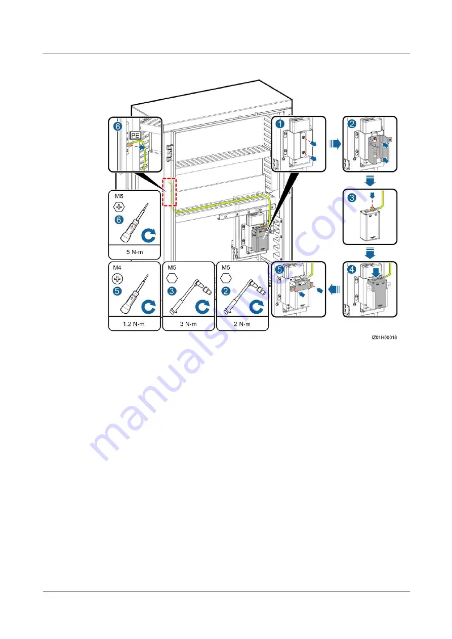
Figure 4-17


Installing a PoE SPD 


----End 

4.5.7 Installing the SIM Card and 4G Antenna 

Installing the SIM Card 

Step 1


Remove the cables preinstalled on the SmartLogger and label the cables. 

Step 2


Take the SmartLogger out of the installation position. 

Step 3


Install the SIM card, reinstall the SmartLogger, and secure the SmartLogger. 

Step 4


Reconnect the cables based on the labels. 

Содержание SmartACU2000D Series

Страница 1: ...SmartACU2000D Smart Array Controller User Manual with No PID Module Issue 01 Date 2020 02 14 HUAWEI TECHNOLOGIES CO LTD ...

Страница 2: ...tomer All or part of the products services and features described in this document may not be within the purchase scope or the usage scope Unless otherwise specified in the contract all statements information and recommendations in this document are provided AS IS without warranties guarantees or representations of any kind either express or implied The information in this document is subject to c...

Страница 3: ...tors and qualified electricians Symbol Conventions The symbols that may be found in this guide are defined as follows Symbol Description Indicates a hazard with a high level of risk which if not avoided will result in death or serious injury Indicates a hazard with a medium level of risk which if not avoided could result in death or serious injury Indicates a hazard with a low level of risk which ...

Страница 4: ...his Document Issue 01 2020 02 14 Copyright Huawei Technologies Co Ltd iii Change History Updates between document issues are cumulative The latest document issue contains all the changes in earlier issues Issue 01 2020 02 14 This issue is used for first office application FOA ...

Страница 5: ...nt 5 2 Overview 7 2 1 Model 7 2 2 Product Introduction 8 2 3 Appearance 11 2 3 1 Product Appearance 11 2 3 2 Enclosure Signs 13 2 4 Product Composition 14 2 5 Working Principles 18 2 6 Configuration in Different Scenarios 21 2 6 1 Fiber Ring Network 21 2 6 2 4G LTE 25 2 6 3 4G 28 3 Storage Requirements 31 4 System Installation 32 4 1 Checking Before Installation 32 4 2 Tools 32 4 3 Installation Re...

Страница 6: ...Cable Without a PoE SPD 59 5 7 Connecting the Three Phase AC Power Cable 60 5 8 Connecting the Peripheral RS485 Communications Cables 61 5 9 Optional Connecting the Peripheral Network Cable 63 5 10 Optional Connecting the DC Output Power Cable to the 24 V Power Module 64 5 11 Connecting the Single Phase Power Cable 65 5 12 Connecting DO DI AI Cables 66 6 System Commissioning 68 6 1 Checking Before...

Страница 7: ...SmartACU2000D Smart Array Controller User Manual with No PID Module Contents Issue 01 2020 02 14 Copyright Huawei Technologies Co Ltd vi 8 Technical Specifications 82 A Acronyms and Abbreviations 84 ...

Страница 8: ...ome faulty and the resulting equipment malfunction component damage personal injuries or property damage are not covered under the warranty Follow local laws and regulations when installing operating or maintaining the equipment The safety instructions in this document are only supplements to local laws and regulations Huawei will not be liable for any consequences of the following circumstances O...

Страница 9: ...h scratches cannot be exposed to an outdoor environment for a long period of time Personal Safety If there is a probability of personal injury or equipment damage during operations on the equipment immediately stop the operations report the case to the supervisor and take feasible protective measures Use tools correctly to avoid hurting people or damaging the equipment Do not touch the energized e...

Страница 10: ...ment is connected permanently to the protective ground Before operating the equipment check its electrical connection to ensure that it is securely grounded General Requirements Before connecting cables ensure that the equipment is intact Otherwise electric shocks or fire may occur Ensure that all electrical connections comply with local electrical standards Ensure that the cables you prepared mee...

Страница 11: ...fire due to high temperature ensure that the ventilation vents or heat dissipation system are not blocked when the equipment is running Do not expose the equipment to flammable or explosive gas or smoke Do not perform any operation on the equipment in such environments 1 5 Mechanical Safety Using Ladders Use wooden or fiberglass ladders when you need to perform live working at heights When a step ...

Страница 12: ... to avoid injury when moving heavy objects When moving the equipment by hand wear protective gloves to prevent injuries 1 6 Commissioning When the equipment is powered on for the first time ensure that professional personnel set parameters correctly Incorrect settings may result in inconsistency with local certification and affect the normal operation of the equipment 1 7 Maintenance and Replaceme...

Страница 13: ...Module 1 Safety Precautions Issue 01 2020 02 14 Copyright Huawei Technologies Co Ltd 6 If the equipment is faulty contact your dealer The equipment can be powered on only after all faults are rectified Failing to do so may escalate faults or damage the equipment ...

Страница 14: ...document covers the following product models SmartACU2000D D 00 SmartACU2000D D 02 SmartACU2000D D 05CN Figure 2 1 Model identifiers Table 2 1 Model description No Meaning Description 1 Series SmartACU2000 smart array controller 2 Hardware D version D 3 Voltage level D 800 V three phase AC input 4 Configuration 00 one MBUS route 02 two MBUS routes 05CN one MBUS route and 4G antenna ...

Страница 15: ...pecifications 3 Compliance symbols 4 Company name and country of origin The nameplate figure is for reference only 2 2 Product Introduction Functions The SACU is an outdoor cabinet that houses the SmartLogger3000 SmartLogger for short 4G antenna SmartModule1000 Ethernet switch access terminal box ATB and power over Ethernet PoE module The SmartLogger monitors and manages PV power systems It conver...

Страница 16: ...ables implementing MBUS networking Features Intelligent and flexible Connects to a maximum of 150 solar inverters and supports one click commissioning Easy to use Supports wizard based settings facilitating parameter settings and device connection Stable and reliable Has a built in surge protection module The industrial application is secure and reliable Networking Figure 2 3 Networking of the Sma...

Страница 17: ...onnect to devices such as solar inverters environmental monitoring instruments EMIs and power meters Multiple optical fiber ring networks can be connected to the management system over an Ethernet switch Wireless network 4G LTE solution The IP address of the SmartLogger and that of the customer premises equipment CPE must be on the same network segment Figure 2 4 Networking of the SmartACU2000D D ...

Страница 18: ...le optical fiber ring networks can be connected to the management system over an Ethernet switch Wireless network 4G solution 2 3 Appearance 2 3 1 Product Appearance Appearance Figure 2 5 Appearance No Component Description 1 Cabinet door 2 Mounting plate 3 Waterproof connector for the protective earthing cable PE Specifications 3 4 in Inner diameter 13 18 mm 0 51 0 71 in 4 Waterproof connectors f...

Страница 19: ...s upgrade and data export Ensure that the USB cover is tightened when the port is idle 9 Waterproof connectors for the RS485 communications cable or network cable RS485 ETH Specifications 3 4 in Inner diameter 13 18 mm 0 51 0 71 in 10 Ventilation valve 11 Waterproof connector for the single phase AC power cable AC INPUT Specifications 3 4 in Inner diameter 13 18 mm 0 51 0 71 in 12 Waterproof conne...

Страница 20: ...cal technicians are allowed to install and operate the device Warning label for multiple power inputs This device has more than one power input Before maintenance ensure that the upstream switch is OFF Warning label for cable connection Do not connect a three phase input power cable to a single phase input switch Do not connect a single phase input power cable to a three phase input switch Otherwi...

Страница 21: ...auxiliary tools or by more than one person 2 4 Product Composition For simplicity purposes the following figure shows only the components that you need to operate and reserved installation positions Figure 2 7 SmartACU2000D D 02 Components Table 2 2 Components and reserved installation positions No Name Specifications Quantity 1 Power adapter of the SmartLogger U01 AC input 100 240 V 50 Hz 60 Hz D...

Страница 22: ...A 8 20 μs 4P 1 5 Three phase SPD 1 F01 Uc 680 V AC 20 kA 40 kA 8 20 μs 1P 4 6 Three phase SPD 2 F02 Uc 680 V AC 20 kA 40 kA 8 20 μs 1P 4 7 Position for the Ethernet switch SWITCH 1 8 SmartMBUS CCO MBUS CCO SmartMBUS CCO01A 1 9 SmartLogger3000 SmartLogger SmartLogger3000 1 10 Fiber adapter OFA01 TX1 RX1 OFA02 TX2 RX2 2LC PC 2LC PC 4 2 11 Position for the SPD of the power over Ethernet PoE module 1 ...

Страница 23: ... 50 Hz 60 Hz DC output 12 V 2 A 1 2 Position for the 24 V DC power module U02 AC input 100 240 V 50 Hz 60 Hz DC output 12 V DC 60 W maximum 24 V DC 30 W maximum NOTE If an external 24 28 V DC input is used the DC output voltage ranges from 21 5 V to 25 2 V The 24 V DC power module is optional Its installation position is reserved in the cabinet 1 3 AC input terminal of the 24 V power module JX02 2...

Страница 24: ...485 communications terminal JX01 12P supports the wires with a cross sectional area ranging from 1 mm2 to 2 5 mm2 or 18 14 AWG 1 18 Position for the SmartModule1000A01 SmartModule 1 19 Protective earthing PE bar 1 Only the SmartACU2000D D 00 provides the installation positions for the longitudinal encryption device fiber ring network switch and auxiliary power supply which can be installed on a gu...

Страница 25: ...icates with devices in a PV array over RS485 MBUS or Ethernet When the SACU communicates with solar inverters over MBUS log in to the embedded WebUI of the SmartLogger3000 choose Monitoring MBUS Networking Settings and set Networking to Enable default value When the SACU communicates with the solar inverters over RS485 set Networking to Disable For details see the SmartLogger3000 User Manual RS485...

Страница 26: ... 2 10 RS485 communication mode All SACU models support the RS485 communication mode The SmartLogger connects to the transformer station power meter solar inverter MBUS CCO module and other devices that support RS485 communication over COM ports The figure displays only major components and cables and is for reference only MBUS communication mode ...

Страница 27: ... the three phase AC power cable In the SACU that supports the access of two MBUS routes the MBUS CCO module connects to the solar inverters that support MBUS communication over the three phase AC power cable The MBUS CCO module is available only for the SmartACU2000D D 02 The figure displays only major components and cables and is for reference only Ethernet communication mode All SACU models supp...

Страница 28: ...to the plant monitoring system by optical fibers through an ATB Over a 4G LTE network All SACU models support the 4G LTE communication mode The cabinet reserves positions for installing the PoE module and PoE SPD The SmartLogger connects to the plant monitoring system by 4G LTE through CPE 4G communication mode The SmartLogger communicates with the cloud server over a 4G wireless network 2 6 Confi...

Страница 29: ...ed area the figure does not show all factory installed components and cables Table 2 4 Components required in the fiber ring network scenario Position Component Recommended Model or Specifications Componen t Source Quantity SACU Optional SmartModule SmartModule1000A01 Purchased from Huawei 1 Optional Ethernet switch UT H605 or ES1000 1 Optional 24 V power supply 1 Fitting bag for optical ring swit...

Страница 30: ...ide of the transformer station is greater than 600 V and less than or equal to 800 V the rated voltage of the knife fuse switch should be greater than or equal to 800 V Recommended rated current of the fuse 32 A rated current of the knife fuse switch box 32 A number of poles 3 three fuses for each knife fuse switch box Scenario with a double colu mn transformer 1 Scenario with a dual split transfo...

Страница 31: ...Cat 5e outdoor shielded network cable with an outer diameter of less than 9 mm 0 35 in and internal resistance of less than or equal to 1 5 ohms 10 m 1 5 ohms 32 81 ft as well as shielded RJ45 connectors 3 Peripheral RS485 communications cable Computer cable DJYP2VP2 22 2x2x1 or armored shielded twisted pair that can be used outdoors as well as OT M4 terminals 0 5 1 mm2 1 mm2 20 18 AWG 18 AWG 4 Ca...

Страница 32: ...ng diagram Components in dashed line boxes are optional To highlight the involved area the figure does not show all factory installed components and cables Table 2 6 Components required in the 4G LTE network scenario Position Component Recommended Model or Specifications Compo nent Source Quantity SACU Optional SmartModule SmartModule1000A01 Purchas ed from Huawei 1 Optional 24 V power supply 1 Fi...

Страница 33: ... the LV side of the transformer station is less than or equal to 600 V the rated voltage of the knife fuse switch should be greater than or equal to 600 V When the rated AC voltage on the LV side of the transformer station is greater than 600 V and less than or equal to 800 V the rated voltage of the knife fuse switch should be greater than or equal to 800 V Recommended rated current of the fuse 3...

Страница 34: ...S485 communicatio ns cable Computer cable DJYP2VP2 22 2x2x1 or armored shielded twisted pair that can be used outdoors as well as OT M4 terminals 0 5 1 mm2 1 mm2 20 18 AWG 18 AWG 3 Cabinet PE cable Outdoor copper cable and OT M6 terminals 6 16 mm2 16 mm2 10 6 AWG 6 AWG 4 Network cable from the PoE module or PoE SPD to the CPE 20 m 65 62 ft long network cable delivered with the Huawei CPE If the ca...

Страница 35: ...io Figure 2 14 Networking diagram Table 2 8 Components required in the 4G network scenario Position Component Recommended Model or Specifications Componen t Source Quantity SACU Optional Ethernet switch UT H605 or ES1000 Purchased from Huawei 1 Optional SmartModule SmartModule1000A01 1 Optional 24 V power supply 1 SIM Card Standard SIM card of a local carrier size 25 mm x 15 mm Prepared by the cus...

Страница 36: ... 600 V the rated voltage of the knife fuse switch should be greater than or equal to 600 V When the rated AC voltage on the LV side of the transformer station is greater than 600 V and less than or equal to 800 V the rated voltage of the knife fuse switch should be greater than or equal to 800 V Recommended rated current of the fuse 32 A rated current of the knife fuse switch box 32 A number of po...

Страница 37: ...r than or equal to 1000 V 8 10 mm2 10 mm2 8 AWG 2 Optional Peripheral network cable Cat 5e outdoor shielded network cable with an outer diameter of less than 9 mm 0 35 in and internal resistance of less than or equal to 1 5 ohms 10 m 1 5 ohms 32 81 ft as well as shielded RJ45 connectors 3 Peripheral RS485 communications cable Computer cable DJYP2VP2 22 2x2x1 or armored shielded twisted pair that c...

Страница 38: ...ically If any rodent bites are found replace the packing materials immediately Store the SACU in a place with appropriate temperature and humidity to protect the SACU from dust and water vapor corrosion To avoid personal injury or device damage stack SACUs neatly so that they will not fall over If the SACU has been stored for a long time it needs to be inspected by professionals before it is put i...

Страница 39: ... is intact If any damage is found do not use the device and contact your dealer as soon as possible Deliverables Check the number of deliverables against the packing list in the packing case If any deliverables are missing or damaged contact your dealer 4 2 Tools Category Tool Installation Hammer drill Drill bit Φ14 mm 0 55 in and Φ16 mm 0 63 in Adjustable wrench Open end 32 mm 12 59 in Flat head ...

Страница 40: ...logies Co Ltd 33 Category Tool Rubber mallet Crimping tool Cable cutter Utility knife RJ45 crimping tool Network cable tester Multimeter SPD extracting tool Heat shrink tubing Heat gun Vacuum cleaner Marker Measuring tape Level Cable tie Personal protective equipment PPE Safety gloves Safety goggles Anti dust respirator Safety boots ...

Страница 41: ...U2000D Smart Array Controller User Manual with No PID Module 4 System Installation Issue 01 2020 02 14 Copyright Huawei Technologies Co Ltd 34 4 3 Installation Requirements Figure 4 1 Installation requirements ...

Страница 42: ...mplate 4 4 1 Wall mounted Installation Step 1 Determine the positions for drilling holes into the wall based on the delivered marking off template For details see Figure 4 2 Level the marking off template using a level and mark mounting holes using a marker Step 2 Drill holes using a hammer drill and install expansion bolts Avoid drilling holes into the water pipes and power cables buried in the w...

Страница 43: ...ure the hole distances If the holes are inaccurately positioned drill holes again Level the head of the expansion sleeve with the concrete wall after removing the bolt spring washer and flat washer Otherwise the mounting bracket will not be securely installed on the wall Figure 4 3 Drilling holes and installing expansion bolts Step 3 Assign two persons to lift the cabinet and mount it on the bolts...

Страница 44: ...Co Ltd 37 Figure 4 4 Installing a cabinet End 4 4 2 Support mounted Installation Step 1 Determine the positions for drilling holes into the support based on the delivered marking off template For details see Figure 4 2 Level the marking off template using a level and mark mounting holes using a marker Step 2 Drill holes using a hammer drill ...

Страница 45: ...tem Installation Issue 01 2020 02 14 Copyright Huawei Technologies Co Ltd 38 Figure 4 5 Drilling a hole Step 3 Insert the M12x40 bolt assemblies delivered with the cabinet into the holes and secure them using the supplied nuts and flat washers Do not fully tighten the bolts ...

Страница 46: ...allation Issue 01 2020 02 14 Copyright Huawei Technologies Co Ltd 39 Figure 4 6 Fixing bolts Step 4 Assign two persons to lift the cabinet and mount it on the bolts and assign another person to assist Step 5 Tighten the bolts using a torque wrench with the open end of 18 mm 0 71 in ...

Страница 47: ...re pole mounting brackets based on the dimensions of the SACU For details about the dimensions see Dimensions You are advised to use M12 U shaped bolts to secure the pole mounting brackets Figures provided in this section are for reference only The actual poles and pole mounting brackets prevail Step 1 Secure the pole mounting brackets to the pole and tighten the U shaped bolts to a torque of 45 N...

Страница 48: ...System Installation Issue 01 2020 02 14 Copyright Huawei Technologies Co Ltd 41 Figure 4 8 Securing pole mounting brackets Step 2 Secure the SACU to the pole mounting brackets For detailed operations see 4 4 2 Support mounted Installation Figure 4 9 Securing a cabinet End ...

Страница 49: ...take protective measures to prevent rain or snow from entering the cabinet If it is impossible to take protective measures do not open the main cabinet door on rainy or snowy days Do not leave unused screws in the cabinet Loosen the screws on the main cabinet door open the cabinet door and adjust the support bar Figure 4 10 Opening a cabinet door To highlight the involved area the figure does not ...

Страница 50: ...odule Step 5 Connect the GE4 port on the SmartModule to the LAN port on the SmartLogger using the network cable delivered with the SmartModule Step 6 Connect the preinstalled RS485 cable to the COM port on the SmartLogger based on the label Step 7 Connect the preinstalled power cable to the 12V 1A port on the SmartModule based on the cable label Figure 4 12 Connecting a cable End ...

Страница 51: ...tch will be installed Step 2 Secure the Ethernet switch Step 3 Connect a PE cable to the Ethernet switch Figure 4 13 Installing an Ethernet switch Step 4 Connect the FE1 port on the Ethernet switch to the WAN port on the SmartLogger using the network cable delivered with the Ethernet switch Step 5 Connect the preinstalled power cable to the 12VDC 1A port on the Ethernet switch based on the label F...

Страница 52: ... delivered with the 24 V power module Step 4 Install the 24 V power module in the cabinet Step 5 Connect the AC input power cable delivered with the SACU to the 24 V power module based on the cable label Figure 4 15 Installing a 24 V power module End 4 5 5 Installing the PoE Module Step 1 Loosen screws do not remove the screws and remove the mounting board Step 2 Remove screws from the PoE module ...

Страница 53: ...the nuts on the PoE SPD mounting board Do not remove the nuts Step 2 Replace and secure the PoE SPD mounting bracket Step 3 Connect one end of the ground cable to the PE point on the PoE SPD and secure the ground nut Step 4 Place the PoE SPD in the mounting bracket Ensure that the PE point faces upwards and the surface marked PE faces outwards Step 5 Secure the PoE SPD fastener Step 6 Connect the ...

Страница 54: ... Installing a PoE SPD End 4 5 7 Installing the SIM Card and 4G Antenna Installing the SIM Card Step 1 Remove the cables preinstalled on the SmartLogger and label the cables Step 2 Take the SmartLogger out of the installation position Step 3 Install the SIM card reinstall the SmartLogger and secure the SmartLogger Step 4 Reconnect the cables based on the labels ...

Страница 55: ...2 14 Copyright Huawei Technologies Co Ltd 48 Figure 4 18 Installing a SIM card End Installing the 4G Antenna Step 1 Remove the 4G antenna bound inside the cabinet Step 2 Install the 4G antenna on the cabinet Step 3 Connect the cable to the 4G port on the SmartLogger Figure 4 19 Installing a 4G antenna End ...

Страница 56: ...t signal cables single phase AC power cables and three phase AC power cables reversely or mix them up Otherwise the caused equipment damage is not covered under any warranty or service agreement For simplicity purposes cables described in this chapter are those to be connected onsite rather than factory installed cables The cabling routes are for reference only The cable colors shown in the electr...

Страница 57: ... cable is available Step 1 Remove the locking cap and plug from the waterproof connector Step 2 Route the cable through the locking cap and then the waterproof connector Figure 5 1 Routing a cable Step 3 Connect the cable and tighten the locking cap Step 4 Check that the cable is connected correctly and securely Seal the waterproof connector and cable hole using the supplied firestop putty Step 5 ...

Страница 58: ...he waterproof connector Step 2 Secure the tube fitting using the nut delivered with the tube Figure 5 3 Installing a tube fitting Step 3 Route the cable through the tube conduit and then the fitting and connect the cable Step 4 Secure the fitting to the conduit Step 5 Check that the cable is connected correctly and securely Then take appropriate measures to ensure that the tube conduit and fitting...

Страница 59: ...g a cable The cavity formed after the conductor crimp strip of the OT terminal is crimped must wrap the core wires completely The core wires must contact the OT terminal closely Wrap the wire crimping area with heat shrinkable tubing or PVC insulation tape The heat shrink tubing is used as an example When using a heat gun protect the devices from being scorched Figure 5 4 Crimping an OT terminal 5...

Страница 60: ...nce the corrosion resistance of a ground terminal you are advised to apply silica gel or paint on it after connecting the ground cable Figure 5 5 Connecting a PE cable 5 4 Connecting the Communications Cables for the Fiber Ring Network Connecting the Optical Jumpers Step 1 Obtain optical modules from the fitting bag for optical ring switching Step 2 Insert an optical module into the SFP1 or SFP2 p...

Страница 61: ...ide with a label faces downward Snap the optical module into place Then pull it back to ensure that it is secure Step 3 Connect the optical jumpers delivered with the optical modules to the ports on the optical modules Figure 5 6 Connecting optical jumpers 1 Optical module 2 Optical jumper End Connecting the Cables to the ATB As optical cables are hard prepare optical cables before routing them in...

Страница 62: ...2020 02 14 Copyright Huawei Technologies Co Ltd 55 Figure 5 7 ATB interior 1 Fiber spool 2 Fixing points for internal steel wires of optical cables 3 Cable clip Step 1 Remove the external mechanical parts from the ATB Figure 5 8 Removing external mechanical parts Step 2 Remove the optical cable fastener ...

Страница 63: ...e optical jumper through the cable hole on the side of the ATB and connect the cable to the ATB Step 5 Connect the peripheral optical cable to the ATB splice the optical cable and the optical jumper and wind the spliced cable around the fiber spool on the ATB Only professionals are allowed to splice fibers Figure 5 10 Connecting optical cables Step 6 Check that the cables are connected correctly a...

Страница 64: ...e with a PoE SPD Step 1 Connect the POE port on the PoE module to the PROTECT port on the PoE SPD using the network cable delivered with the PoE SPD Figure 5 11 Connecting a PoE module to a PoE SPD Step 2 Connect the factory installed network cable on the SmartLogger to the DATA port on the PoE module Step 3 Connect the factory installed power cable on the SmartLogger to the PoE module ...

Страница 65: ... 5 Electrical Connections Issue 01 2020 02 14 Copyright Huawei Technologies Co Ltd 58 Figure 5 12 Connecting cables to the PoE module Step 4 Connect the network cable delivered with the CPE to the Surge port on the PoE SPD Figure 5 13 Connecting a CPE network cable End ...

Страница 66: ...hout a PoE SPD Step 1 Connect the factory installed network cable on the SmartLogger to the DATA port on the PoE module Step 2 Connect the factory installed power cable on the SmartLogger to the PoE module Figure 5 14 Connecting cables to the PoE module Step 3 Connect the network cable delivered with the CPE to the PoE port on the PoE module Figure 5 15 Connecting a CPE network cable End ...

Страница 67: ...ct the three phase AC power cable for the SACU that supports the access of two MBUS routes For details about the single MBUS route situation refer to the way of connecting the first route of three phase AC power cable Step 1 Prepare a cable Figure 5 16 Length for cable stripping Step 2 Connect the L1 L2 and L3 wires to the three phase input switch Connect the L1 1 L2 1 and L3 1 wires from the FU01...

Страница 68: ...pheral RS485 communications cables to the JX01 terminal block All RS485 communications cables are connected in the same way This section describes how to connect two RS485 communications cables Table 5 1 Definition of the JX01 terminal block No Port on the JX01 Terminal Block Definition 1 RS485 1 RS485A RS485 differential signal 2 RS485 1 RS485B RS485 differential signal 3 RS485 2 RS485A RS485 dif...

Страница 69: ...al 12 RS485 6 RS485B RS485 differential signal For the SACU that supports the access of two MBUS routes do not connect a peripheral RS485 communications cable to the RS485 3 port ports 5 and 6 on the JX01 terminal block because the communications cable of the MBUS CCO module has been connected to this port JX01 ports 7 8 9 10 11 and 12 can be connected to the RS485 cable only after the SmartModule...

Страница 70: ...etwork cables to ports FE2 to FE5 on the Ethernet switch All network cables can be connected in the same way Step 1 Prepare a network cable Figure 5 20 Wiring sequence of an RJ45 connector 1 White and orange 2 Orange 3 White and green 4 Blue 5 White and blue 6 Green 7 White and brown 8 Brown Verify that the network cable functions properly using a network cable tester Step 2 Connect the peripheral...

Страница 71: ...yright Huawei Technologies Co Ltd 64 Figure 5 21 Connecting a network cable End 5 10 Optional Connecting the DC Output Power Cable to the 24 V Power Module Step 1 Prepare a cable Figure 5 22 Length for cable stripping Step 2 Connect the cable to the 24V OUT and 24V OUT ports on the power module Step 3 Bind the cable ...

Страница 72: ...g a DC output power cable to the 24 V power module End 5 11 Connecting the Single Phase Power Cable Step 1 Prepare a cable Figure 5 24 Length for cable stripping Step 2 Connect the cable to the single phase input switch Connect the L and N L wires to the L and N L terminals of the station service power source for the transformer station through an MCB Step 3 Bind the cable ...

Страница 73: ...Technologies Co Ltd 66 Figure 5 25 Connecting a cable End 5 12 Connecting DO DI AI Cables The SACU reserves the waterproof connectors for the DO DI and AI cables Cabling routes are provided for the signal cables For details about how to prepare and connect the cables see the SmartPID2000 User Manual and SmartLogger3000 User Manual ...

Страница 74: ...SmartACU2000D Smart Array Controller User Manual with No PID Module 5 Electrical Connections Issue 01 2020 02 14 Copyright Huawei Technologies Co Ltd 67 Figure 5 26 Cabling routes ...

Страница 75: ...ng for the power cables and signal cables meets the requirements for routing strong current and weak current cables and complies with the cable routing plan 6 The locking caps of the used waterproof connectors are tightened and sealed Idle waterproof connectors are plugged and the locking caps are tightened 7 The cabinet interior is clean without dust dirt or foreign matter 8 The paint on the cabi...

Страница 76: ... MBUS routes turn on the corresponding three phase power switches Step 3 Check that the input voltages of all switches of the SACU are within appropriate operating voltage ranges using a multimeter Step 4 Turn on the QF03 single phase input switch in the SACU Step 5 Turn on the three phase input switch in the SACU If the SACU supports the access of one MBUS route turn on the FU01 switch If the SAC...

Страница 77: ...tch that controls the power supply from the remote transformer station to the SACU If the SACU supports the access of one MBUS route turn off the corresponding three phase power switch If the SACU supports the access of two MBUS routes turn off the corresponding three phase power switches Step 3 Turn off the QF03 single phase input switch in the SACU Step 4 Turn off the three phase input switch in...

Страница 78: ...o take protective measures do not open the cabinet door on rainy or snowy days Table 7 1 Maintenance checklist Check Item Check That Maintenance Interval Cabinet The SACU exterior is not damaged or deformed There is no dust or dirt in the SACU Once every twelve months System running status All devices in the SACU operate properly The SPD works properly Once every six months Electrical connections ...

Страница 79: ...ule is not powered on The power cable of the PoE module is loose or disconnected If the cable is loose or disconnected secure it The power adapter or 24 V DC power module fails to supply power 1 The input and output power cables of the 24 V DC power module are loose or disconnected 2 The power adapter or 24 V DC power module is faulty 1 If the cable is loose or disconnected secure it 2 Replace the...

Страница 80: ...martLogger WebUI over the LAN port default IP address of the LAN port 192 168 8 10 and check whether the IP address of the SmartLogger is correct If not set the IP address again 4 Connect the PC to the Ethernet switch and ping the IP address of the SmartLogger If the communication is abnormal replace the network cable and try again No communication between the SmartLogger and the SmartModule 1 The...

Страница 81: ... a component check the SACU before powering it on to ensure that the new component works properly Dispose of faulty components in accordance with the local disposal act for waste electrical equipment 7 3 1 Replacing the Single Three Phase SPD An SPD consists of a surge protection module and a base If an SPD is damaged or its indication window is displayed in red the SPD is deemed unavailable and n...

Страница 82: ...Figure 7 2 Installing a new surge protection module End 7 3 2 Replacing the Knife Fuse Switch Step 1 Disconnect the cables from the knife fuse switch and label the cables Step 2 Remove the faulty knife fuse switch Figure 7 3 Removing a faulty knife fuse switch Step 3 Install a new knife fuse switch Step 4 Connect the cables based on their labels End ...

Страница 83: ...fuse switch box End 7 3 4 Replacing the Single Phase Input Switch Step 1 Disconnect the cables from the single phase input switch and label the cables Step 2 Remove the faulty single phase input switch Figure 7 5 Removing a faulty single phase input switch Step 3 Install a new single phase input switch Step 4 Connect the cables based on their labels End 7 3 5 Replacing the SmartMBUS CCO Module Ste...

Страница 84: ...lacing a faulty SmartMBUS CCO module Step 3 Install the mounting ears on a new SmartMBUS CCO module Step 4 Installing a new SmartMBUS CCO module Step 5 Connect the cables based on their labels End 7 3 6 Replacing the SmartLogger Step 1 Disconnect the cables from the SmartLogger and label the cables Step 2 Remove the faulty SmartLogger and its cabinet mounting kit ...

Страница 85: ...uawei Technologies Co Ltd 78 Figure 7 7 Removing a faulty SmartLogger Step 3 Remove the mounting ears and guide rail mounting kit from a new SmartLogger and install the cabinet mounting kit Figure 7 8 Replacing a SmartLogger Step 4 Install the new SmartLogger in the cabinet Step 5 Connect the cables based on their labels ...

Страница 86: ... Step 1 Disconnect the cables from the power adapter and label the cables Step 2 Remove the faulty power adapter Figure 7 9 Removing a faulty power adapter Step 3 Install a new power adapter Step 4 Connect the cables based on their labels End 7 3 8 Replacing the Fiber Adapter Step 1 Disconnect the cables from the fiber adapter and label the cables Step 2 Remove the faulty fiber adapter ...

Страница 87: ...ht Huawei Technologies Co Ltd 80 Figure 7 10 Removing a fiber adapter Step 3 Install a new fiber adapter Step 4 Connect the cables based on their labels End 7 3 9 Replacing the USB Port Step 1 Disconnect the cable from the USB port and label the cable Step 2 Remove the faulty USB port Figure 7 11 Removing a USB port ...

Страница 88: ...ith No PID Module 7 System Maintenance Issue 01 2020 02 14 Copyright Huawei Technologies Co Ltd 81 Step 3 Ensure that the rubber ring is on the inner side of the cabinet when installing a new USB port Step 4 Connect the cables based on their labels End ...

Страница 89: ...three phase Three phase input power 5 W maximum 5 W maximum 2 x 5 W maximum Single phase operating voltagea AC input 100 240 V Single phase input power 110 W maximum Frequency 50 Hz 60 Hz Cable routing mode Routed in and out from the bottom Operation and maintenance mode Operated and maintained from the front Operating environment Indoor and outdoor Maximum operating altitude 4000 m 13123 36 ft In...

Страница 90: ...rtACU2000D D 02 Net weight including firestop putty screws and the mounting plate About 30 kg 66 14 lb About 29 kg 63 93 lb About 32 kg 70 55 lb Enclosure ingress protection IP rating IP65 IP65 Type 4X Operating humidity 4 100 RH Operating temperature 40 C to 60 C 40 F to 140 F Storage temperature 40 C to 70 C 40 F to 158 F Note a Supports a 24 V power system DC input and output 24 28 V DC 70 W ma...

Страница 91: ...es Co Ltd 84 A Acronyms and Abbreviations A AC alternating current AI analog input APP application ATB access terminal box C CAT 5E Category 5 enhanced CCO central controller CPE customer premises equipment D DC direct current DI digital input DO digital output E EMI environmental monitoring instrument ETH Ethernet L LTE Long Term Evolution M ...

Страница 92: ...and Abbreviations Issue 01 2020 02 14 Copyright Huawei Technologies Co Ltd 85 MBUS monitoring bus P PE protective earthing PoE power over Ethernet R RH relative humidity S SFP small form factor pluggable SPD surge protective device W WEEE waste electrical and electronic equipment ...

Отзывы: