Installation Manual – Antenna & Feeder System Installation
BTS3802C & RRU
Chapter 2
Installing RF Antenna & Feeder System
2-43
(1)
(2)
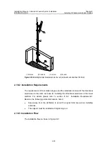
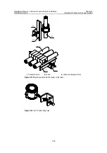
(1) Expansion bolt M8
×
80
(2) Panel of the feeder window
Figure 2-40
Installation of the feeder window
2.15 Leading Feeders into Equipment Room
Generally, the feeder window installed in the equipment room is of 12-hole type.
Therefore, this section only describes how to lead the feeders into the equipment
room through the 12-hole feeder window. As for the 27-hole feeder window, take this
section for reference.
2.15.1 Principles of Arrangement
z
There are 4 large openings in a 12-hole feeder window. Each opening is divided
into 3 holes, each for one feeder.
z
The feeders shall be laid out in clockwise or counter clockwise according to their
numbers in the three small holes of the same opening.
z
The layout of the feeders shall facilitate expansion, since the layout in the feeder
window cannot be changed during expansion, instead, it is only possible to add
feeders in the feeder window or to change the jumper connection on the device.
z
The feeder layout in the feeder window shall facilitate the layout on the cabling
rack and the connection on the set top. The feeders shall be in parallel with no
intertwining.
2.15.2 Installation Procedures
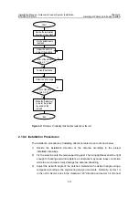
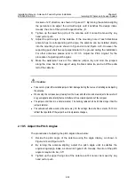
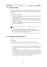
1) Lead each feeder into the equipment room through the feeder window. During
the operation, some personnel shall provide cooperation in the room lest the
feeders damage the indoor equipment.
2) Make the waterproof curves of the feeders outside the feeder window.


