background image

FusionModule800 Smart Small Data Center 
Maintenance Guide 

5 Parts Replacement 


Issue 02 (2016-11-15) 

Huawei Proprietary and Confidential                                     

Copyright © Huawei Technologies Co., Ltd. 

66 


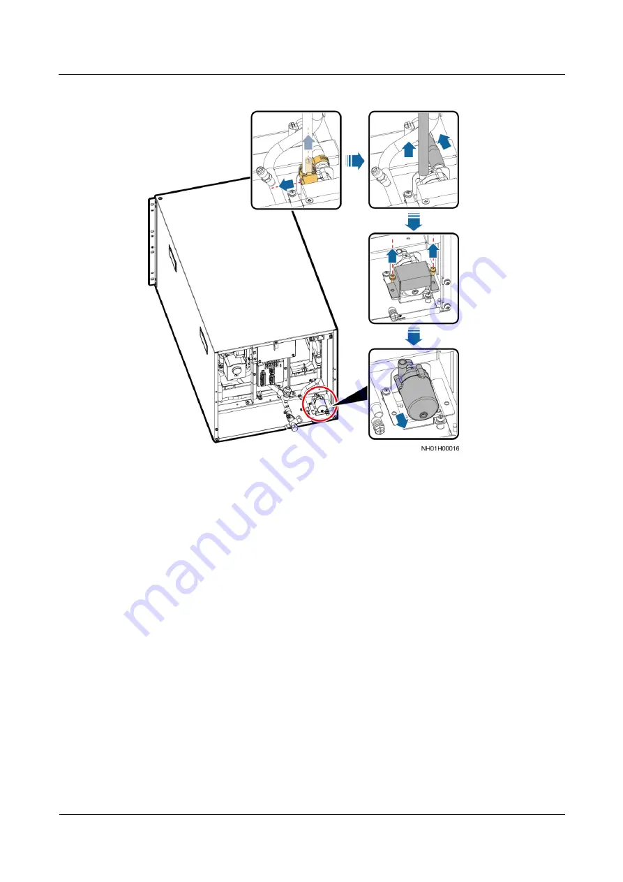
Figure 5-30


Removing a humidifier pump 


Step 7


Install the new humidifier pump by performing the preceding steps in reverse order, connect 
the hoses, and install hose clamps. 

Step 8


Clear up the humidifier pump total runtime. 


Method 1: Log in to the ECC800 mobile phone or pad app as admin. 

a.


Choose 

Home

b.


Tap the cabinet that houses the air conditioner in the micro-module view. 

c.


Tap the air conditioner to be set in the cabinet layout diagram. 

d.


Choose 

Real-time Data

 > 

Perf Maint

, clear up the humidifier pump total running 

time. 


Method 2: Log in to the ECC800 WebUI as admin. Choose 

Monitoring

 > 

Air 

Conditioner

 > 

NetCol5000-A0104

 > 

Controls

 > 

Performance Maint Ctrl

, clear up the 

humidifier pump total running time. 

----End 

5.3.1.5 Replacing a Wet Film Humidifier 

Prerequisites 


Tool: Phillips screwdriver. 

Содержание FusionModule800

Страница 1: ...FusionModule800 Smart Small Data Center V100R001 Maintenance Guide Issue 02 Date 2016 11 15 HUAWEI TECHNOLOGIES CO LTD ...

Страница 2: ... Huawei and the customer All or part of the products services and features described in this document may not be within the purchase scope or the usage scope Unless otherwise specified in the contract all statements information and recommendations in this document are provided AS IS without warranties guarantees or representations of any kind either express or implied The information in this docum...

Страница 3: ... potential risks promptly Intended Audience This document is intended for Marketing engineers Technical support engineers System engineers Hardware installation engineers Commissioning engineers Data configuration engineers Maintenance engineers Symbol Conventions The symbols that may be found in this document are defined as follows Symbol Description Indicates an imminently hazardous situation wh...

Страница 4: ...ddress practices not related to personal injury Calls attention to important information best practices and tips NOTE is used to address information not related to personal injury equipment damage and environment deterioration Change History Changes between document issues are cumulative The latest document issue contains all the changes made in earlier issues Issue 02 2016 11 15 This issue is the...

Страница 5: ... Components in the Bearing System 28 5 1 1 Replacing a Fan Assembly 28 5 1 2 Replacing a Door Status Sensor 29 5 1 3 Replacing a PDU2000 31 5 2 Parts Replacement for the Power Supply and Distribution System 32 5 2 1 Replacing a Surge Protection Module 32 5 2 2 Replacing a Fuse 34 5 2 3 Replacing an Indicator 36 5 2 4 Replacing a UPS2000 G 38 5 2 5 Replacing a Power Distribution Subrack 41 5 2 6 Re...

Страница 6: ...ents 76 5 3 2 1 Replacing an Outdoor Fan 77 5 3 2 2 Replacing a Compressor 80 5 3 2 3 Replacing a Filter Dryer 82 5 3 2 4 Replacing a High Pressure Sensor 84 5 3 2 5 Replacing an Oil Heating Belt 85 5 3 2 6 Replacing a Pneumatic Switch 86 5 3 2 7 Replacing a Safety Valve 87 5 4 Replacing Monitoring System Components 88 5 4 1 Replacing a CIM 89 5 4 2 Replacing BIMs 90 5 4 3 Replacing an ECC800 Main...

Страница 7: ...se and verify that the component to be replaced is powered off Assess impact on the system before switching off the general input circuit breaker or turning off the cooling system during parts replacement Do not install or remove power cables for a device which is powered on Transient contact between the core of the power cable and the conductor may generate electric arcs or sparks which may cause...

Страница 8: ...n system See the documents delivered with the IDS800 FusionModule800 Smart Small Data Center V100R001 Installation Guide Provides guidance about Smart Module installation and commissioning Downloaded from http support huawei com UPS2000 G 6 kVA 20 kVA User Manual Describes the UPS installation operation and maintenance Downloaded from http support huawei com RMS MODBUS01A User Manual Describes the...

Страница 9: ...Co Ltd 3 Tool Name Specifications and Appearance Adjustable wrench 6 Socket wrench M6 M8 M12 Electric screwdriver Heat gun Reducing valve Electrician s knife Impact tool Insulation tape Needle nose pliers Diagonal pliers RJ11 crimping tool Crimping tool Wire stripper Hydraulic pliers Wire clippers Nylon cable tie Multimeter Electroprobe Insulation tester N A N A ...

Страница 10: ...l configuration and structural layout of the Smart Module Experience in maintaining the Smart Module Power supply and distribution system Familiar with the power supply and distribution system configurations and the operations for each core component in the Smart Module With power distribution system engineer qualifications Cooling system Familiar with the cooling system configurations and the ope...

Страница 11: ...everity Possible Cause Measures Surge protective device SPD SPD fault Major A surge protection module is damaged or the SPD circuit breaker has tripped Replace the surge protection module or switch on the SPD circuit breaker Automatic transfer switch ATS ATS No Voltage alarm 1 on the display Major The ATS upstream switch is not turned on The controller power cable is not connected The input power ...

Страница 12: ...he mains voltage is high ATS parameters are not set properly 1 Switch to the backup power supply 2 Ensure that ATS parameters are set properly ATS Open Phase alarm 4 on the display Major The input power cable is loose or not connected Check that the input power cable is properly connected ATS Three Phase Voltage Imbalance alarm 5 on the display Major The mains is of poor quality Rectify the mains ...

Страница 13: ...fication loads The output carries the transformer load but the transformer mode is not enabled The hardware is damaged Rectify the fault and power on the UPS again Check that the load types are supported by the UPS Enable the transformer mode Contact Huawei technical support Internal fault Critical The bypass input cable connection does not match the output system Correct the bypass input cable co...

Страница 14: ...ttery monitoring system Communication Failure Critical The network cable communication is interrupted Check the cable connection to the smart ETH gateway BCB Tripping Critical The battery has discharged to the end of disch arge EOD threshold The battery circuit breaker BCB box is manually disconnecte d There is a security risk in the battery loop Identify the alarm cause rectify the fault and swit...

Страница 15: ...ssible Cause Measures Single Batt Exception Critical The battery shell is broken resulting in electrolyte and electricity leakage The battery loop cable is broken and short circuit ed to the ground resulting in electricity leakage Check whether the appearances of abnormal batteries are intact and replace abnormal batteries Check whether battery loop cables are deteriorated or broken and replace fa...

Страница 16: ...temperature exceeds the upper threshold 4 The return air high temperature alarm threshold is inappropriat e 5 The temperature displayed on the LCD is different from the actual temperature 1 Add air conditioners 2 Check whether other causes exist if the alarm is not cleared in a long period after startup 3 Measure the ambient temperature 4 Adjust the return air high temperature alarm threshold 5 Ca...

Страница 17: ...The supply air temperature is higher than the upper threshold during startup 3 The ambient temperature exceeds the upper threshold 4 The supply air high temperature alarm threshold is inappropriat e 5 The temperature displayed on the LCD is different from the actual temperature 1 Add air conditioners 2 Check whether other causes exist if the alarm is not cleared in a long period after startup 3 Me...

Страница 18: ...ensor is improper 2 The ambient temperature exceeds the upper threshold 3 The cold aisle high temperature alarm threshold is inappropriat e 4 The temperature and humidity displayed on the LCD is different from the actual temperature and humidity 5 The thermal load power is high or the cooling capacity is insufficient 1 Adjust the installation position of the T H sensor 2 Measure the ambient temper...

Страница 19: ...midity displayed on the LCD is different from the actual temperature and humidity 5 The thermal load power is high or the cooling capacity is insufficient 1 Adjust the installation position of the T H sensor 2 Measure the ambient temperature 3 Adjust the hot aisle high temperature alarm threshold 4 Maintain or replace the T H sensor 5 Add air conditioners Comp drive comm failed Critical 1 The comp...

Страница 20: ...configured the condensate pump may be faulty or the condensate pump draining capacity declines 4 If a condensate pump is configured the condensate pump drainpipe may be blocked 5 If no condensate pump is configured maybe the automatic drainage port is blocked an internal drainpipe is blocked or a drainpipe is frozen 1 Check the cables to the high liquid level detector 2 Maintain or replace the hig...

Страница 21: ...d 1 Maintain or replace the indoor fan 2 Check cables to the indoor fan EEV high overheating locked Critical 1 The electronic expansion valve coil is loose 2 The electronic expansion valve coil is faulty 3 The electronic expansion valve is faulty 1 Reinstall the electronic expansion valve coil 2 Replace the electronic expansion valve coil 3 Replace the electronic expansion valve EEV auto control f...

Страница 22: ...rature alarm Critical 1 The ambient temperature is higher than the upper threshold 2 There is strong radiation on the monitoring point resulting in high temperature 3 The temperature displayed on the LCD is different from the actual temperature 1 Measure the ambient temperature 2 Install an awning 3 Calibrate or replace the temperature sensor EEV driver power off Critical The electronic expansion ...

Страница 23: ...he power supply and distribution system When a UPS is faulty alarm information is displayed on the LCD Critical alarms must be handled before powering on the UPS again Otherwise the fault may be extended or the UPS may be damaged If the fault is not rectified contact Huawei technical support Table 4 1 Troubleshooting power supply and distribution equipment Symptom Possible Cause Measure The rear e...

Страница 24: ...wer source 1 or 2 The ATS signal cable is loose The ATS control loop switch is not turned on The ATS fuse has blown The fault information displayed on the controller is not cleared The ATS handle is not pulled out Connect and secure the ATS signal cable Turn on the ATS control loop switch Replace the blown ATS fuse Rectify faults for the controller Remove the ATS handle The ATS button mode and aut...

Страница 25: ...acing a Fuse Set the switching delay and close the automatic switch to O The surge protection function fails The SPD circuit breaker is not turned on The SPD ground cable is not connected The surge protection module is abnormal The SPD window is red Check that the SPD circuit breaker is turned on The power distribution subrack monitoring type will prompt an alarm indicating that the SPD circuit br...

Страница 26: ...odbus card from the UPS and reinstall it in the corresponding slot in the UPS Add the UPS on the ECC800 WebUI The UPS does not report faults but has no output voltage The output power cable is not securely connected Check the output power cable connection The UPS does not start after you press is not pressed long enough Press for more than 5 seconds until you hear a beep sound The UPS is overloade...

Страница 27: ...y is incorrectly set Save data and shut down primary loads immediately to avoid data loss or damage Connect the UPS input to the backup AC power supply immediately Verify that the number of batteries and battery capacity are correctly set based on the actual configuration You forget the password None If you forget only the LCD password the preset password is 000001 use the feature code the preset ...

Страница 28: ...se Measure Ind oor unit The indoor unit fails to start The indoor fan is damaged Replace the indoor fan by following instructions in 5 3 1 2 Replacing an Indoor Fan The connection terminals for the fans are not securely connected Secure the connection terminals The heating function fails The electric heater temperature switch is protected Check the temperature switch If it is protected due to high...

Страница 29: ...p by following instructions in 5 3 1 3 Replacing a Condensate Pump Cable connection between the liquid level detector and the humidifier float is improper or the device is faulty Check the alarm Check cable connections for high and low liquid level detectors Check whether the liquid level detectors are damaged If necessary replace the liquid level detectors by referring to 5 3 1 7 Replacing a Liqu...

Страница 30: ... The compressor does not work Check whether the compressor driver is faulty Replace the compressor if it is faulty The compres sor discharg e tempera ture is too high The refrigerant loop or component is blocked Clean the loop and components The outdoor units are not installed in right positions The installation distances should meet requirements Install outdoor units in the right positions based ...

Страница 31: ...ector to check for any leakage If leaking points are found retrieve the refrigerant and weld the leaking points again Contact Huawei technical support The condensing pressure is too low Check whether the outdoor temperature is too low and whether the outdoor fan is under control Liquid is returnin g to the compres sor The indoor temperature is too low Increase the temperature setting The air filte...

Страница 32: ...or PSUs Symptom Possible Cause Measure The Power indicator green is off No AC input Check whether the AC input is abnormal PSU fault Replace the PSU The Alarm indicator yellow is steady on Overtemperature protection The ambient temperature exceeds the upper threshold Increase the cooling capacity of the air conditioner The air channel is blocked Unblock it AC input overvoltage or undervoltage prot...

Страница 33: ...ing for the monitoring module No Symptom Possible Cause Measure 1 The Run indicator green is off There is no AC input If the green indicators on PSUs are steady on the power input to the system is normal Otherwise rectify power grid faults The monitoring module is faulty or not securely installed Reinstall the monitoring module If the fault persists replace the monitoring module 2 RJ45 power outpu...

Страница 34: ...ing System 5 1 1 Replacing a Fan Assembly Prerequisites Tools Phillips screwdriver step ladder Materials A spare fan assembly of the same model is available and functional Procedure Step 1 Remove the power cable from the faulty fan assembly When removing cables label the cables with corresponding terminal ports for later connection Step 2 Remove the faulty fan assembly from the top of the aisle co...

Страница 35: ...dity sensor T H sensor When removing cables label the cables with corresponding terminal ports for later connection Step 4 Install the new fan assembly on the top of the aisle containment using a Phillips screwdriver Step 5 Connect the power cable to the new fan assembly End 5 1 2 Replacing a Door Status Sensor Prerequisites Tools Phillips screwdriver insulation tape step ladder Materials A spare ...

Страница 36: ...Door status sensor installation position 1 Door status sensor installation position Procedure Step 1 Remove the cover of the door status sensor manually Step 2 Remove the communications cable using a Phillips screwdriver and insulate the cable When removing cables label the cables with corresponding terminal ports for later connection When removing cables wrap bare cables with insulation tape to a...

Страница 37: ...ver step ladder Materials A spare PDU2000 of the same model is available and functional Context The PDU2000 is installed near the rear door of the cabinet Procedure Step 1 Open the rear door of the cabinet Step 2 Turn off the output circuit breaker of the power distribution subrack corresponding to the PDU2000 and remove the power cable from the terminal block at the top of the PDU2000 Step 3 Remo...

Страница 38: ...ent before replacing a power supply and distribution component Check whether the front and rear ends of the component to be replaced are powered off using a multimeter and electrical tester pen after the component is powered off 5 2 1 Replacing a Surge Protection Module Prerequisites Do not replace a surge protection module during a thunderstorm Before replacing a surge protection module wear prot...

Страница 39: ...e L1 L2 L3 and N voltages to the PE using an electrical tester pen to check whether there is voltage as shown in Figure 5 5 and verify that the faulty SPD has no voltage before replacing the faulty surge protection module Figure 5 5 Detecting voltages Step 4 Hold the faulty surge protection module and pull it out as shown in Figure 5 6 During replacement do not touch the electriferous components i...

Страница 40: ...insulation gloves Materials A new fuse is intact and has the same model as the old fuse Context The fuse is located near the rear door of the Converged Cabinet as shown in Figure 5 7 Fuses can be replaced in a similar way The figures show how to replace a fuse on a 15 kW 6 U PDU In the ATS input scenario the fuses of the indicators and the ATS control loop are located on the right side at the rear...

Страница 41: ...onfidential Copyright Huawei Technologies Co Ltd 35 Figure 5 7 Fuse positions FU1 FU3 Fuses of yellow green and red indicators respectively The figures are for reference only The actual product appearance prevails Procedure Step 1 Shake the fuse terminal block gently pull it out and push it outwards as shown in Figure 5 8 ...

Страница 42: ...imeter step ladder Materials A spare indicator of the same model is available and functional Context There are two types of indicator scenarios independent indicators and indicators configured in the ATS PDU They can be replaced in the same way This section describes how to replace an indicator in the independent indicator scenario Procedure Step 1 Open the rear door of the Converged Cabinet push ...

Страница 43: ...or of the Converged Cabinet remove the protective panel of the ATS PDU and remove the indicator panel as shown in Figure 5 10 This step is performed only when an ATS PDU is configured Figure 5 10 Removing the indicator panel of the ATS PDU Step 4 Loosen the screw at the back of the indicator using a Phillips screwdriver and remove the cables as shown in Figure 5 11 When removing cables label the c...

Страница 44: ...ts up properly Step 9 Reinstall the protective panel End 5 2 4 Replacing a UPS2000 G Prerequisites Tools electroprobe insulation gloves Phillips screwdriver multimeter Materials A spare UPS of the same model is available and functional The UPS is damaged or faulty and cannot work Scenario with One UPS Step 1 Ensure that the TN system is reliably grounded and that the main ground cable of the Smart...

Страница 45: ... Install the new UPS and screw it to the cabinet Step 8 Connect the input power cable output power cable and signal cables to the UPS in sequence Check whether the cable labels are consistent with the silk screens on the UPS and whether all cables are connected Do not connect the manual bypass switch MBS signal cable to the UPS rear at present Step 9 Close the UPS input switch When the output swit...

Страница 46: ...Remove screws from the UPS front panel and pull out the UPS Step 7 Install the new UPS and screw it to the cabinet Step 8 Connect the input power cable output power cable and signal cables to the UPS in sequence Check whether the cable labels are consistent with the silk screens on the UPS and whether all cables are connected Step 9 Close the UPS input and output switches If the UPSs are connected...

Страница 47: ...ignal cables to the UPS in sequence Check whether the cable labels are consistent with the silk screens on the UPS and whether all cables are connected Do not connect the manual bypass switch MBS signal cable to the UPS rear at present Step 9 Close the input switches of the two UPSs When the output switches are off start the inverter After checking that the UPSs start normally shut down the invert...

Страница 48: ... cabinets must be turned off Ensure that the input is disconnected during replacement Procedure Step 1 Replace the 15 kW 6 U PDU 1 Turn off the battery switch 2 Open the front and rear doors of the Converged Cabinet Remove the input power cable UPS input and output power cables air conditioner power cable IT cabinet power cable and signal cable from the rear of the PDU After removing cables wrap e...

Страница 49: ...nected 6 Turn on the battery switch and perform power on commissioning on the PDU 7 Check whether the UPS generates abnormal alarms If there are alarms clear them and start the UPS If there are alarms clear them by referring to UPS2000 G 6 kVA 20 kVA User Manual and start the UPS Step 2 Replace the ATS PDU 1 Turn off the battery switch 2 Open the front and rear doors of the Converged Cabinet and r...

Страница 50: ...tes abnormal alarms If the ATS generates abnormal alarms clear them by referring to the product documentation delivered with the device 7 Start the UPS in inverter mode and turn on the battery switch End 5 2 6 Replacing a Pad Power Socket Prerequisites Before replacement ensure that the input switch is OFF Tools electroprobe insulation gloves Phillips screwdriver Materials A spare pad power socket...

Страница 51: ...he Modbus card Step 2 Remove the Modbus card and remark the DIP switch position Step 3 Set the DIP switch in new Modbus card base on the recorded information Step 4 Install a new Modbus card Step 5 Install the signal cables to the Modbus card base on the recorded information Step 6 Add UPS on the WebUI End 5 2 8 Replacing an ATS Controller Prerequisites Tools electroprobe insulation gloves Phillip...

Страница 52: ...nt panel from the ATS PDU Step 3 Remove cables from the top of the ATS controller as shown by 1 in Figure 5 15 After removing cables wrap exposed terminals with insulation tape and do not block cable labels If cable labels are blocked cables may be connected incorrectly Figure 5 15 Removing an ATS controller Step 4 Remove the screws securing the ATS controller and ATS PDU as shown by 2 in Figure 5...

Страница 53: ...bles to the ATS controller Step 8 Check whether the ATS controller generates abnormal alarms Clear alarms if there is any Step 9 Reinstall the front panel on the ATS PDU and close the front door of the cabinet End 5 2 9 Replacing a Contactor Prerequisites Tools electroprobe insulation gloves Phillips screwdriver multimeter Materials A spare contactor of the same model is available and functional T...

Страница 54: ... top of the contactor as shown by 1 in Figure 5 17 When removing cables label the cables with corresponding terminal ports for later connection Figure 5 17 Removing cables Step 5 Remove screws from the contactor and remove the faulty contactor as shown by 2 in Figure 5 17 Step 6 Install the new contactor in the cabinet by referring to the preceding steps Step 7 Connect the cables to the contactor ...

Страница 55: ...h trip board is damaged or faulty and cannot work The figures are for reference only The actual product appearance prevails Procedure Step 1 Determine the position of the faulty battery switch trip board and open the corresponding cabinet door Step 2 Remove the front panel of the battery cabinet circuit breaker using a Phillips screwdriver as shown in Figure 5 18 Figure 5 18 Removing the front pan...

Страница 56: ...he front panel on the circuit breaker and close the corresponding cabinet door End 5 2 11 Replacing a Battery Switch Tripper Prerequisites The battery switch of the battery cabinet must be disconnected When there are multiple battery strings connected in parallel all battery switches need to be disconnected Ensure that all battery switches are disconnected during replacement Tools electroprobe ins...

Страница 57: ...ch If the voltage is lower than 36 V DC for 1 minute replace the battery switch tripper Step 4 Remove the panel from the MCCB Step 5 Remove the three screws from the MCCB cover using a Phillips screwdriver and remove the cover as shown in Figure 5 20 Figure 5 20 Removing an MCCB cover Step 6 Remove the two signal cables that are located in the left fitting subrack inside the switch and one screw f...

Страница 58: ...xiliary contact and open the corresponding cabinet door Step 2 Remove the front panel of the battery cabinet circuit breaker using a Phillips screwdriver as shown in Figure 5 18 Step 3 Switch a multimeter to the DC voltage mode to measure the voltage between positive and negative copper bars at the upper part of the battery switch If the voltage is lower than 36 V DC for 1 minute replace the batte...

Страница 59: ...er using a Phillips screwdriver as shown in Figure 5 18 Step 3 Switch a multimeter to the DC voltage mode to measure the voltage between positive and negative copper bars at the upper part of the battery switch If the voltage is lower than 36 V DC for 1 minute replace the battery MCCB Step 4 Remove the battery switch tripper by referring to 5 2 11 Replacing a Battery Switch Tripper Step 5 Remove t...

Страница 60: ...el is available and functional The battery MCB is damaged or faulty and cannot work The figures are for reference only The actual product appearance prevails Procedure Step 1 Determine the position of the faulty battery MCB and open the corresponding cabinet door Step 2 Remove the front panel from the battery cabinet MCB using a Phillips screwdriver as shown in Figure 5 21 Figure 5 21 Removing the...

Страница 61: ...inals When removing cables label the cables with corresponding terminal ports for later connection Figure 5 22 Removing a battery MCB Step 5 Push the buckle at the battery MCB outwards using a flat head screwdriver and remove the faulty battery MCB Step 6 Install the new battery MCB by referring to the preceding method connect cables and tighten screws Step 7 Reinstall the removed components and c...

Страница 62: ... and functional The battery current sensor is damaged or faulty and cannot work The figures are for reference only The actual product appearance prevails Procedure Step 1 Determine the position of the faulty battery current sensor and open the corresponding cabinet door Step 2 Remove the front panel of the battery cabinet circuit breaker using a Phillips screwdriver as shown in Figure 5 18 Step 3 ...

Страница 63: ...or cut off the cable ties and remove the faulty battery current sensor as shown by 2 in Figure 5 23 Step 6 Install the new battery current sensor by referring to the preceding method and connect cables Keep the Up arrow on the current sensor of the positive battery copper bar downwards and keep the Up arrow on the current sensor of the negative battery copper bar upwards Step 7 Reinstall the remov...

Страница 64: ...ei Technologies Co Ltd 58 Figure 5 24 Indoor unit components rear 1 Differential pressure switch 2 Electric control box 3 Dehumidification solenoid valve 4 High liquid level detector 5 Low liquid level detector 6 Condensate pump 7 Low pressure sensor 8 Wet film humidifier optional 9 Electronic expansion valve 10 Humidifier float 11 Humidifier pump ...

Страница 65: ... The left one at the bottom is fan 2 and the right one at the bottom is fan 4 5 3 1 1 Replacing a Return Air Filter Prerequisites Tool Phillips screwdriver A return air filter needs to be replaced A spare return air filter of the same model is available and functional Context The return air filter is maintained from the rear Procedure Step 1 Loosen no need to remove the screw on the baffle plate u...

Страница 66: ...r conditioner in the micro module view c Tap the air conditioner to be set in the cabinet layout diagram d Choose Real time Data Perf Maint clear up the air filter total running time Method 2 Log in to the ECC800 WebUI as admin Choose Monitoring Air Conditioner NetCol5000 A0104 Controls Performance Maint Ctrl clear up the air filter total running time 0104 in NetCol5000 A0104 is variable and subje...

Страница 67: ...cabinet that houses the air conditioner in the micro module view c Tap the air conditioner to be set in the cabinet layout diagram d Choose Real time Data OFF Method 2 Log in to the ECC800 WebUI as admin Choose Monitoring Air Conditioner NetCol5000 A0104 Controls Ctrl Info set On off status on EMS Off and then click Submit 0104 in NetCol5000 A0104 is variable and subject to changes with the air co...

Страница 68: ...d Step 4 Remove the four M4 screws from the fan baffle plate using a Phillips screwdriver and remove the fan baffle plate as shown in Figure 5 28 Step 5 Optional Cut the cable tie securing the NTC sensor on fan 2 using scissors or diagonal pliers and remove the NTC sensor The NTC sensor bound to fan 2 needs to be removed when only fan 2 is replaced Step 6 Cut the cable tie securing the fan termina...

Страница 69: ...the micro module view c Tap the air conditioner to be set in the cabinet layout diagram d Choose Real time Data Perf Maint clear up the indoor fan total runtime Method 2 Log in to the ECC800 WebUI as admin Choose Monitoring Air Conditioner NetCol5000 A0104 Controls Performance Maint Ctrl clear up the indoor fan total runtime End 5 3 1 3 Replacing a Condensate Pump Prerequisites Tool Phillips screw...

Страница 70: ...he displayed value prevails Step 2 Disconnect the power supply from the air conditioner control unit after the air conditioner shuts down over the EMS Step 3 Remove the return air filter by referring to 5 3 1 1 Replacing a Return Air Filter Step 4 Remove the top metal sheet of the condensate pump as shown in Figure 5 29 Figure 5 29 Removing a condensate pump Step 5 Remove the hose clamps at the wa...

Страница 71: ... in to the ECC800 mobile phone or pad app as admin a Choose Home b Tap the cabinet that houses the air conditioner in the micro module view c Tap the air conditioner to be set in the cabinet layout diagram d Choose Real time Data OFF Method 2 Log in to the ECC800 WebUI as admin Choose Monitoring Air Conditioner NetCol5000 A0104 Controls Ctrl Info set On off status on EMS Off and then click Submit ...

Страница 72: ...ump total runtime Method 1 Log in to the ECC800 mobile phone or pad app as admin a Choose Home b Tap the cabinet that houses the air conditioner in the micro module view c Tap the air conditioner to be set in the cabinet layout diagram d Choose Real time Data Perf Maint clear up the humidifier pump total running time Method 2 Log in to the ECC800 WebUI as admin Choose Monitoring Air Conditioner Ne...

Страница 73: ...he air conditioner over the EMS Method 1 Log in to the ECC800 mobile phone or pad app as admin a Choose Home b Tap the cabinet that houses the air conditioner in the micro module view c Tap the air conditioner to be set in the cabinet layout diagram d Choose Real time Data OFF Method 2 Log in to the ECC800 WebUI as admin Choose Monitoring Air Conditioner NetCol5000 A0104 Controls Ctrl Info set On ...

Страница 74: ...module view c Tap the air conditioner to be set in the cabinet layout diagram d Choose Real time Data Perf Maint clear up the wet film humidifier total running time Method 2 Log in to the ECC800 WebUI as admin Choose Monitoring Air Conditioner NetCol5000 A0104 Controls Performance Maint Ctrl clear up the wet film humidifier total running time Step 9 After starting the air conditioner and ensuring ...

Страница 75: ...tioner in the micro module view c Tap the air conditioner to be set in the cabinet layout diagram d Choose Real time Data OFF Method 2 Log in to the ECC800 WebUI as admin Choose Monitoring Air Conditioner NetCol5000 A0104 Controls Ctrl Info set On off status on EMS Off and then click Submit 0104 in NetCol5000 A0104 is variable and subject to changes with the air conditioner connection sequence The...

Страница 76: ...icro module view c Tap the air conditioner to be set in the cabinet layout diagram d Choose Real time Data Perf Maint clear up the electric heater total running time Method 2 Log in to the ECC800 WebUI as admin Choose Monitoring Air Conditioner NetCol5000 A0104 Controls Performance Maint Ctrl clear up the electric heater total running time End 5 3 1 7 Replacing a Liquid Level Detector Prerequisite...

Страница 77: ...inet that houses the air conditioner in the micro module view c Tap the air conditioner to be set in the cabinet layout diagram d Choose Real time Data OFF Method 2 Log in to the ECC800 WebUI as admin Choose Monitoring Air Conditioner NetCol5000 A0104 Controls Ctrl Info choose On off status on EMS Off and then click Submit 0104 in NetCol5000 A0104 is variable and subject to changes with the air co...

Страница 78: ...tep 6 Remove screws from the high liquid level detector using a Phillips screwdriver and remove the high liquid level detector Loosen the screws on the low liquid level detector move it upwards and remove it as shown in Figure 5 35 Figure 5 35 Removing a liquid level detector Step 7 Install the new liquid level detector in the original position by performing the steps in reverse order and connect ...

Страница 79: ...he ECC800 mobile phone or pad app as admin a Choose Home b Tap the cabinet that houses the air conditioner in the micro module view c Tap the air conditioner to be set in the cabinet layout diagram d Choose Real time Data OFF Method 2 Log in to the ECC800 WebUI as admin Choose Monitoring Air Conditioner NetCol5000 A0104 Controls Ctrl Info set On off status on EMS Off and then click Submit 0104 in ...

Страница 80: ...essure switch and take out the faulty differential pressure switch Step 8 Set the pressure to 300 Pa for the new differential pressure switch Step 9 Install the new differential pressure switch in the original position by performing the preceding steps in reverse order and connect cables End 5 3 1 10 Replacing a PSU Prerequisites A PSU needs to be replaced A spare PSU of the same model is availabl...

Страница 81: ...ir conditioner over the EMS Method 1 Log in to the ECC800 mobile phone or pad app as admin a Choose Home b Tap the cabinet that houses the air conditioner in the micro module view c Tap the air conditioner to be set in the cabinet layout diagram d Choose Real time Data OFF Method 2 Log in to the ECC800 WebUI as admin Choose Monitoring Air Conditioner NetCol5000 A0104 Controls Ctrl Info set On off ...

Страница 82: ...r in the micro module view c Tap the air conditioner to be set in the cabinet layout diagram d Choose Real time Data ON Method 2 Log in to the ECC800 WebUI as admin Choose Monitoring Air Conditioner NetCol5000 A0104 Controls Ctrl Info set On off status on EMS On and then click Submit End 5 3 2 Replacing Outdoor Unit Components Do not maintain or replace outdoor units during thunderstorms Otherwise...

Страница 83: ... 6 L 30 x 0 05 Figure 5 39 shows the components of an outdoor unit Figure 5 39 Outdoor unit components 1 Outdoor fan blade 2 Safety valve 3 High pressure switch 4 Low pressure switch 5 Low pressure sensor 6 Compressor 7 Oil heating belt 5 3 2 1 Replacing an Outdoor Fan Prerequisites An outdoor fan needs to be replaced A spare outdoor fan of the same model is available and functional Context Tools ...

Страница 84: ...in to the ECC800 WebUI as admin Choose Monitoring Air Conditioner NetCol5000 A0104 Controls Ctrl Info set On off status on EMS Off and then click Submit 0104 in NetCol5000 A0104 is variable and subject to changes with the air conditioner connection sequence The displayed value prevails Step 2 Disconnect the power supplies from the air conditioner control unit and the outdoor unit after the air con...

Страница 85: ...tion in the electric control box Step 7 Secure the outdoor fan cable using cable ties Step 8 Install the blades front panel left front panel and top cover Step 9 Clear up the outdoor fan total runtime Method 1 Log in to the ECC800 mobile phone or pad app as admin a Choose Home b Tap the cabinet that houses the air conditioner in the micro module view c Tap the air conditioner to be set in the cabi...

Страница 86: ...le phone or pad app as admin a Choose Home b Tap the cabinet that houses the air conditioner in the micro module view c Tap the air conditioner to be set in the cabinet layout diagram d Choose Real time Data OFF Method 2 Log in to the ECC800 WebUI as admin Choose Monitoring Air Conditioner NetCol5000 A0104 Controls Ctrl Info set On off status on EMS Off and then click Submit 0104 in NetCol5000 A01...

Страница 87: ...al insulation foam power cables and labels take protective measures such as spreading wet cloth around the welding position Step 8 Remove the three nuts shown by 3 in Figure 5 42 from the compressor base using a 13 mm socket wrench and remove the compressor Figure 5 42 Compressor position 1 Welding point for the suction pipe 2 Compressor 3 Nuts on the compressor base 4 Oil separator 5 Welding poin...

Страница 88: ...time Method 1 Log in to the ECC800 mobile phone or pad app as admin a Choose Home b Tap the cabinet that houses the air conditioner in the micro module view c Tap the air conditioner to be set in the cabinet layout diagram d Choose Real time Data Perf Maint clear up the compressor total runtime Method 2 Log in to the ECC800 WebUI as admin Choose Monitoring Air Conditioner NetCol5000 A0104 Controls...

Страница 89: ...he power supplies from the air conditioner control unit and the outdoor unit after the air conditioner shuts down over the EMS Step 3 Reclaim all the refrigerant from the system using a refrigerant retrieval device to ensure that there is no pressure inside the system Discharge the refrigerant if the local laws and regulations allow Step 4 Loosen the screws using a Phillips screwdriver and remove ...

Страница 90: ...er checking that the air conditioner does not leak vacuumize the air conditioner and charge refrigerant Step 10 Reinstall the left front panel and left rear panel End 5 3 2 4 Replacing a High Pressure Sensor Prerequisites A high pressure sensor needs to be replaced A spare high pressure sensor of the same model is available and functional Context Tools Phillips screwdriver refrigerant retrieval de...

Страница 91: ...nditioner shuts down over the EMS Step 3 Open the top cover and right rear panel Step 4 Cut the cable ties on the high pressure sensor cable using diagonal pliers and take out the high pressure sensor cable from the electric control box Step 5 Remove the high pressure sensor using an adjustable wrench Figure 5 39 shows the position of the high pressure sensor Step 6 Apply sealant to the threads to...

Страница 92: ... 5 Open and take out the cable tie of the oil heating belt Figure 5 39 shows the position of the oil heating belt Step 6 Install the new oil heating belt and secure it using a cable tie Step 7 Reinstall the oil heating belt cable in the electric control box and secure it using a cable tie Step 8 Reinstall the left front panel and top cover End 5 3 2 6 Replacing a Pneumatic Switch Prerequisites The...

Страница 93: ...inside the system Discharge the refrigerant if the local laws and regulations allow Step 4 Open the top cover and right rear panel Step 5 Cut the cable ties on the pneumatic switch cable using diagonal pliers and take out the pneumatic switch cable from the electric control box Step 6 Remove the pneumatic switch using a welding torch Figure 5 39 shows the positions of the high pressure and low pre...

Страница 94: ... air conditioner connection sequence The displayed value prevails Step 2 Disconnect the power supplies from the air conditioner control unit and the outdoor unit after the air conditioner shuts down over the EMS Step 3 Reclaim all the refrigerant from the system using a refrigerant retrieval device to ensure that there is no pressure inside the system Discharge the refrigerant if the local laws an...

Страница 95: ...ent detection cable from the HALL port on the CIM 2 Remove the BCB cable from the BCB_1 port on the CIM 3 Remove the communications cable from the POE port on the CIM If multiple CIMs are cascaded remove all cables and label them Step 3 Remove the CIM 1 Remove the CIM from the fastener as shown in Figure 5 44 Figure 5 44 Removing a CIM 2 Record the DIP switch address of the CIM Step 4 Install a CI...

Страница 96: ... parameters are cleared to the fastener Step 4 Connect one end of the BIM cable to the pin port on the BIM Step 5 Press the networking switch on the replacement BIM based on the corresponding battery number The RUN indicator changes from steady green to steady red After you release the networking switch the RUN indicator changes to blinking green intermittently at super short intervals then to bli...

Страница 97: ...Step 6 fails replace the BIM again by following the instructions in this section By default the BIM checks the battery internal resistance once every 24 hours The red indicator is steady on during the check You can also choose Monitoring CIM System Running Control on the WebUI and click Internal resistance to manually measure the battery internal resistance The battery internal resistance will cha...

Страница 98: ...main control module Step 3 Remove cables the WiFi module and antennas from the ECC800 main control module Step 4 Loosen the screws on both sides of the ECC800 main control module Step 5 Pull the handles on both sides of the ECC800 main control module and remove the main control module Figure 5 47 Removing the ECC800 main control module Step 6 Take out the Micro SD and SIM cards from the ECC800 mai...

Страница 99: ...rminals in the rear of a removed PSU to avoid electric shocks Tool insulation gloves Materials a reserved undamaged and undeformed PSU of the appropriate model Procedure Step 1 Push the locking latch in the upper right corner of the PSU panel leftwards Step 2 Pull out the handle of the PSU to remove the PSU from the subrack Step 3 Place a reserved PSU at the entry to the subrack push the locking l...

Страница 100: ...ame model is available and functional Context A smart ETH gateway can be installed in the following two positions based on the project conditions If the M shaped cable troughs are deployed for the module install the smart ETH gateway on the M shaped cable trough on the top of the Converged Cabinet as shown in Figure 5 50 Figure 5 50 Position 1 for installing the smart ETH gateway 1 Smart ETH gatew...

Страница 101: ...ht Huawei Technologies Co Ltd 95 Figure 5 51 Position 2 for installing the smart ETH gateway 1 Smart ETH gateway Procedure Step 1 Label each cable based on the corresponding ports on the smart ETH gateway Step 2 Disconnect cables from the smart ETH gateway Step 3 Remove the faulty smart ETH gateway from the guide rail as shown in Figure 5 52 ...

Страница 102: ...rt ETH gateway in the original position and connect the cables End 5 4 6 Replacing ECC800 Antennas Prerequisites Tools ESD wrist strap ESD gloves Materials Spare ECC800 antennas of the same model are available and functional Procedure Step 1 Remove the 2 4G antenna and the cable connected to the RF_Z antenna port on the ECC800 Step 2 Remove the 3G antenna and the cable connected to the 3G 4G anten...

Страница 103: ... the original positions and connect them to the ECC800 as shown in Figure 5 54 Figure 5 54 Installing antennas End 5 4 7 Replacing a Micro SD Card Prerequisites Tools ESD wrist strap ESD gloves Materials A spare Micro SD card of the same model is available and functional Procedure Step 1 Loosen the screws on both sides of the ECC800 main control module Step 2 Pull the handles on both sides of the ...

Страница 104: ...g out the Micro SD card Step 4 Install the spare Micro SD card into the slot Step 5 Install the ECC800 main control module in the card slot Step 6 Tighten the screws on both sides of the ECC800 main control module End 5 4 8 Replacing a WiFi Module Prerequisites Tools ESD wrist strap ESD gloves Materials A spare WiFi module of the same model is available and functional Procedure Step 1 Remove the f...

Страница 105: ...ional Context An external AI DI unit is deployed at the 42 U position on the rear top of the IT cabinet adjacent to the Converged Cabinet For details see Figure 5 57 Figure 5 57 external AI DI unit installation position Procedure Step 1 Remove cables connected to the external AI DI unit When removing cables label the cables with corresponding terminal ports for later connection After removing cabl...

Страница 106: ...t the address for the external AI DI unit to 1 Figure 5 59 Setting an address Step 5 Connect cables to the new external AI DI unit End 5 4 10 Replacing a Camera Prerequisites Recommended tools and materials inner hexagon screwdriver delivered with the product package step ladder 2 m A dome camera needs to be replaced Spare dome cameras of the same model are available and functional Procedure Step ...

Страница 107: ...t Huawei Technologies Co Ltd 101 Figure 5 60 Removing the front cover Step 2 Remove the inner cover as shown in Figure 5 61 Figure 5 61 Removing the inner cover In the scenario with a SD card remove the SD card and install to a new camera Step 3 Remove the screws securing the camera base from the camera mounting plate as shown in Figure 5 62 ...

Страница 108: ... using screws End Follow up Procedure Check whether the new camera works properly and adjust the camera angle If video images are properly displayed on the video screen of the management system client the new camera works properly 5 4 11 Replacing a VCN500 Prerequisites Recommended tools Phillips screwdriver flat head screwdriver A VCN500 needs to be replaced A spare VCN500 of the same model is av...

Страница 109: ...posed terminals with insulation tape and do not block cable labels If cable labels are blocked cables may be connected incorrectly Step 2 Remove the faulty VCN500 from the cabinet Step 3 Place the new VCN500 with caution into the IT cabinet and gently press down buttons on the upper and lower mounting ears as shown in Figure 5 64 Figure 5 64 Placing a VCN500 Step 4 Tighten the captive screws in th...

Страница 110: ...e containment configure one T H sensor for each IT cabinet Converged Cabinet and battery cabinet For the cold aisle containment outside the aisle configure two T H sensors on the top of the Converged Cabinet inside the aisle configure one T H sensor on the air inlet of each IT cabinet network cabinet and battery cabinet A maximum of nine T H sensors can be configured for one module When a T H sens...

Страница 111: ...rap exposed terminals with insulation tape and do not block cable labels If cable labels are blocked cables may be connected incorrectly Step 3 Remove the T H sensor from its base as shown in Figure 5 66 Before removing a T H sensor remember the DIP switch setting on it When you install a new T H sensor you need to set the same DIP switch setting for the new one Figure 5 66 Removing a T H sensor S...

Страница 112: ...1 Cut the cable ties on the temperature sensor using diagonal pliers and remove the network cable from the temperature sensor as shown in Figure 5 67 Figure 5 67 Removing a temperature sensor Step 2 Install the spare temperature sensor bind it to the original position using cable ties and connect cables to it When installing temperature sensors bind the cables behind the sensors to the cable bridg...

Страница 113: ...rature sensor works properly 5 4 14 Replacing a Smoke Detector Prerequisites Recommended tools and materials Phillips screwdriver insulation tape step ladder 2 m A smoke detector needs to be replaced Spare smoke detectors of the same model are available and functional Context The smoke detector is installed in the Converged Cabinet as shown by 1 in Figure 5 68 Figure 5 68 Sensor positions 1 Smoke ...

Страница 114: ...the base by rotating it in a direction opposite to Step 1 End Follow up Procedure Check whether the new smoke detector works properly If its status is displayed on the WebUI of the ECC800 the new smoke detector works properly 5 4 15 Replacing a Water Sensor and Water Detection Rope Prerequisites Recommended tools and materials Phillips screwdriver crimping tool A water sensor needs to be replaced ...

Страница 115: ...Huawei Technologies Co Ltd 109 Figure 5 70 Sensor positions 1 Smoke detector 2 Water detector A water sensor consists of a water detection rope water detector and conversion cable The water detection rope is laid out on the floor connecting to the water detector placed near the collector by the conversion cable Figure 5 71 shows the components ...

Страница 116: ...onversion cable end A connecting to the water detector 3 Conversion cable 4 Conversion cable end B connecting to water the detection rope 5 Water detection rope end A connecting to the conversion cable 6 Water detection rope Procedure Step 1 Replace the water detector 1 Remove the conversion cable at the conversion port for the water detector and conversion cable 2 Remove the cover from the water ...

Страница 117: ...d 111 Figure 5 72 Removing the cover from the water detector 3 Remove the bottom plate of the water detector from the Converged Cabinet as shown in Figure 5 73 Figure 5 73 Removing the bottom plate of the water detector 4 Install the new water detector in the Converged Cabinet by referring to the preceding steps 5 Connect the new water detector to the conversion cable ...

Страница 118: ...wn in Figure 5 75 Figure 5 75 Connecting a new water detection rope 1 Conversion cable end B connecting to the water detection rope 2 Water detection rope end A connecting to the conversion cable The water detection rope and conversion cable are interconnected through the male and female connectors End Follow up Procedure Check whether the new water detector works properly Connect the network cabl...

Страница 119: ...dicators Check the indicators All indicators are normal The power supply is normal Replace the indicator that generates no or dim light Surge protection module Check the surge protection module indicator and miniature circuit breaker MCB status The surge protection module indicator is steady green The MCB is ON If the surge protection module indicator is steady red replace the surge protection mod...

Страница 120: ...iquid crystal display LCD N A According to the status icons on the LCD all units are operating properly No fault or alarm information is found in the active and historical alarm records If an alarm is present rectify the fault by checking the device status and parameters Battery Battery management alarm N A No battery management alarm is generated Identify the cause of an alarm based on the alarm ...

Страница 121: ...tem Operation Expected Result Troubleshootin g Battery operating temperature N A 1 The ambient battery temperature is 25 5 C 2 The battery operating temperature is lower than 45 C 3 Battery charge and discharge conditions meet the requirements specified in the battery specifications 1 Identify the cause of an abnormal battery operating temperature 2 If the fault persists contact Huawei technical s...

Страница 122: ...t terminals and the battery input terminals at the UPS side is greater than 1 of the battery string voltage check whether the cable between the battery string and the UPS is excessively long or the cable diameter is excessively small 2 Check whether the equalized charging voltage and float charging voltage are correctly set for the UPS 3 If the fault persists contact Huawei technical support ECC80...

Страница 123: ...us Monitoring module indicator N A The monitoring module indicator is steady green or blinking green If the indicator is off or any abnormal condition occurs see 4 3 Monitoring System Troubleshooting to rectify the fault Network interface indicator N A The green indicator is steady on and the yellow indicator is blinking Check the network cable connection Monitor interface network management syste...

Страница 124: ...iew the real time monitoring page The monitoring page is properly displayed after you click View If the monitoring page is not displayed after you click View check that the IP address is correctly set and check cable connection or replace the camera For details see 5 4 10 Replacing a Camera The Intelligent Battery Monitoring System Battery management alarm N A No battery management alarm is genera...

Страница 125: ...n Rope The Cooling System Water pan filter N A Check that the water pan filter is clean and not blocked Clean it with water Condensate pan and liquid level detector N A Check that the condensate pan and liquid level detector have no dirt or scale Clean up the dirt and scale from the condensate pan and liquid level detector Humidifier float N A Check that the humidifier float has no dirt or scale C...

Страница 126: ...t 1 Click Running Parameters and choose Diagnostic Mode Para On the Diagnostic Mode Para page set Inlet Solenoid Man Ctrl to On and click Submit Check that there is water in the humidifier water pan 2 On the Diagnostic Mode Para page set Inlet Solenoid Man Ctrl to Off set Humidifier Film Man Ctrl to On and click Submit Choose Running Info Humid Info Circulation Pump Ctrl to check that the humidifi...

Страница 127: ...guard if it is distorted N A Check that the indoor fan blades are intact Replace the fan component if it is damaged N A Check that the operating indoor fan generates no abnormal noise Replace the fan component if it is damaged N A Check that the screws on the indoor fan are not loose or distorted Tighten loose screws Compressor N A Check that the compressor is secured Tighten screws if the compres...

Страница 128: ... protection module Check the surge protection module indicator and miniature circuit breaker MCB status The surge protection module indicator is steady green The MCB is ON If the surge protection module indicator is steady red replace the surge protection module If the MCB is OFF switch it on Emergency fan Check whether the top of the emergency fan is blocked The top of the fan is clean and not bl...

Страница 129: ...ially from the front panel Parameter configuration N A The configuration of the output voltage grade frequency number of batteries and battery capacity meets requirements Reset the parameters Power cables and terminals between the UPS and the power distribution subrack N A The insulation layer of cables is intact and terminals are free from signs of ignition Replace the cables Secure output termin...

Страница 130: ...tem Operation Expected Result Troubleshootin g Battery operating temperature N A 1 The ambient battery temperature is 25 5 C 2 The battery operating temperature is lower than 45 C 3 Battery charge and discharge conditions meet the requirements specified in the battery specifications 1 Identify the cause of an abnormal battery operating temperature 2 If the fault persists contact Huawei technical s...

Страница 131: ...ut terminals at the UPS side is greater than 1 of the battery string voltage check whether the cable between the battery string and the UPS is excessively long or the cable diameter is excessively small 2 Check whether the equalized charging voltage and float charging voltage are correctly set for the UPS 3 If the fault persists contact Huawei technical support Battery management parameter setting...

Страница 132: ...charging voltage and float charging voltage of a battery are normal 2 If the charging voltage of a battery exceeds the specifications requirement perform a complete forcible equalized charging for the battery and check again whether the voltage is normal 3 If the fault persists contact Huawei technical support Shallow discharge test recommended N A Conduct a shallow discharge test when the UPS is ...

Страница 133: ...ermine whether the PSU is faulty If the PSU is faulty replace it Fan N A No abnormal noise is generated If abnormal noise is generated clean the fan Operating environment N A Ambient temperature 20 C to 65 C Humidity 0 95 RH non condensin g If the humidity or temperature is abnormal check the air conditioner status Monitoring module indicator N A The monitoring module indicator is steady green or ...

Страница 134: ...eferences and 4 3 Monitoring System Troubleshooting or contact Huawei technical support Operating environment N A Ambient temperature 20 C to 65 C Humidity 0 95 RH non condensin g If the humidity or temperature is abnormal check the air conditioner status Cable connections N A The cable connections are secure Secure loose cables N A Cables are not damaged Replace damaged cables Camera Camera avail...

Страница 135: ... system is lower than 45 C Find the cause of an abnormal temperature The Water Sensor and Water Detection Rope Water sensor and water detection rope function Place the water detection rope into the water and check whether a water leakage alarm is generated by the water sensor A water leakage alarm is generated If no water leakage alarm is generated replace the water detection rope by referring to ...

Страница 136: ...t Huawei Technologies Co Ltd 130 Maintenance area Item Operation Expected Result Troubleshootin g N A Check that the return air filter is not damaged or distorted If it is damaged replace the air filter by referring to 5 3 1 1 Replacing a Return Air Filter Evaporator N A Check that no foreign matter exists on the evaporator surface Remove foreign matter ...

Страница 137: ...t 1 Click Running Parameters and choose Diagnostic Mode Para On the Diagnostic Mode Para page set Inlet Solenoid Man Ctrl to On and click Submit Check that there is water in the humidifier water pan 2 On the Diagnostic Mode Para page set Inlet Solenoid Man Ctrl to Off set Humidifier Film Man Ctrl to On and click Submit Choose Running Info Humid Info Circulation Pump Ctrl to check that the humidifi...

Страница 138: ...guard if it is distorted N A Check that the indoor fan blades are intact Replace the fan component if it is damaged N A Check that the operating indoor fan generates no abnormal noise Replace the fan component if it is damaged N A Check that the screws on the indoor fan are not loose or distorted Tighten loose screws Compressor N A Check that the compressor is secured Tighten screws if the compres...

Страница 139: ...ircuit breaker MCB status The surge protection module indicator is steady green The MCB is ON If the surge protection module indicator is steady red replace the surge protection module If the MCB is OFF switch it on Emergency fan Check whether the top of the emergency fan is blocked The top of the fan is clean and not blocked Clean dust and foreign matters from the top of the fan Dust inside the p...

Страница 140: ...k Cable insulation performance after power off Measure the insulation resistance using an insulation tester The insulation resistance is greater than or equal to 5 megohms If the cable insulation performance is poor replace the cable Insulation performance of the power distribution subrack after power off Measure the insulation resistance using an insulation tester The insulation resistance is gre...

Страница 141: ...t or alarm information is found in the active and historical alarm records If an alarm is present rectify the fault by checking the device status and parameters Cleanliness N A Wipe the cabinet surface using a white paper and the paper does not turn black Remove the dust especially from the front panel Parameter configuration N A The configuration of the output voltage grade frequency number of ba...

Страница 142: ...ct 3 Batteries are free from damage and cracks 4 Batteries are free from acid leakage 5 Batteries are not deformed or bulged If the battery appearance is abnormal contact Huawei technical support Battery operating temperature N A 1 The ambient battery temperature is 25 5 C 2 The battery operating temperature is lower than 45 C 3 Battery charge and discharge conditions meet the requirements specifi...

Страница 143: ...ut terminals at the UPS side is greater than 1 of the battery string voltage check whether the cable between the battery string and the UPS is excessively long or the cable diameter is excessively small 2 Check whether the equalized charging voltage and float charging voltage are correctly set for the UPS 3 If the fault persists contact Huawei technical support Battery management parameter setting...

Страница 144: ...at charging voltage 2 25 V cell 0 02 V cell 1 Check whether the equalized charging voltage and float charging voltage of a battery are normal 2 If the charging voltage of a battery exceeds the specifications requirement perform a complete forcible equalized charging for the battery and check again whether the voltage is normal 3 If the fault persists contact Huawei technical support Shallow discha...

Страница 145: ...ei technical support Battery connection reliability N A 1 When battery strings are powered off check the reliability of each connection point from positive terminals to negative terminals All points are connected reliably 2 Use a torque wrench to check the tightening torque for each battery screw The torque meets the requirements of the battery manufacturer After checking that the battery screws m...

Страница 146: ...ermine whether the PSU is faulty If the PSU is faulty replace it Fan N A No abnormal noise is generated If abnormal noise is generated clean the fan Operating environment N A Ambient temperature 20 C to 65 C Humidity 0 95 RH non condensin g If the humidity or temperature is abnormal check the air conditioner status Monitoring module indicator N A The monitoring module indicator is steady green or ...

Страница 147: ...rt Operating environment N A Ambient temperature 20 C to 65 C Humidity 0 95 RH non condensin g If the humidity or temperature is abnormal check the air conditioner status Cable connections N A The cable connections are secure Secure loose cables N A Cables are not damaged Replace damaged cables Camera Camera availability On the ECC800 WebUI click Maintenance View Video Video Info to enter the vide...

Страница 148: ...g system is lower than 45 C Find the cause of an abnormal temperature The Water Sensor and Water Detection Rope Water sensor and water detection rope function Place the water detection rope into the water and check whether a water leakage alarm is generated by the water sensor A water leakage alarm is generated If no water leakage alarm is generated replace the water detection rope by referring to...

Страница 149: ...up the dirt and scale from the condensate pan and liquid level detector Humidifier float N A Check that the humidifier float has no dirt or scale Clean up the dirt and scale from the humidifier float Return air filter N A Check that the return air filter is clean and not blocked Clean the air filter with water recommended N A Check that the return air filter is not damaged or distorted If it is da...

Страница 150: ...t 1 Click Running Parameters and choose Diagnostic Mode Para On the Diagnostic Mode Para page set Inlet Solenoid Man Ctrl to On and click Submit Check that there is water in the humidifier water pan 2 On the Diagnostic Mode Para page set Inlet Solenoid Man Ctrl to Off set Humidifier Film Man Ctrl to On and click Submit Choose Running Info Humid Info Humidifier Pump Ctrl to check that the humidifie...

Страница 151: ... fan guard is not distorted Repair or replace the fan guard if it is distorted N A Check that the indoor fan blades are intact Replace the fan component if it is damaged N A Check that the operating indoor fan generates no abnormal noise Replace the fan component if it is damaged N A Check that the screws on the indoor fan are not loose or distorted Tighten loose screws Compressor N A Check that t...

Страница 152: ...c Heater Monitoring unit N A Export air conditioner logs alarms temperature humidity the operating status of the compressor fan electric heater wet film humidifier and water pump and time from the monitoring system View the historical alarms generated in this quarter and select the most common five ones If no monitoring system is available skip this item Rectify the fault or contact Huawei technic...

Страница 153: ...that the surfaces of the control board SPDs and voltage detection boards are not aged Replace the abnormal board N A Check that the electric heater contactor works properly 1 When the air conditioner is on on the Controls page choose Diagnostic Mode Input and click Submit 2 Choose Running Parameters Diagnostic Mode Para set Elec heater manual control to On and click Submit You can hear a click sou...

Страница 154: ... Technologies Co Ltd 148 Maintenance area Item Operation Expected Result Troubleshootin g N A Check that the fan runs properly without abnormal noise or vibration and the blades rotate properly Replace the outdoor fan by following instructions in 5 3 2 1 Replacing an Outdoor Fan N A Check that the fan air intake and exhaust vents are not blocked Clear obstacles ...

Страница 155: ...ight Huawei Technologies Co Ltd 149 B Acronyms and Abbreviations A AC alternating current ATS automatic transfer switch B BCB battery circuit breaker BIB battery control I O board BIM battery interface module C CE ConformitéEuropé enne CIM communication interface module D DC direct current E ECC energy control center ETH Ethernet F FE fast Ethernet ...

Страница 156: ...right Huawei Technologies Co Ltd 150 I iBAT ibattery IT Internet Technology L LED light emitting diode N NetEco network ecosystem NTC negative temperature coefficient P PE protective earthing PoE power over Ethernet S SD secure digital SIM subscriber identity module U UPS uninterruptible power system V VCN video cloud node W WiFi Wireless Fidelity ...

Отзывы: