eSpace IAD
Troubleshooting
3 Co mmon Troubleshooting Methods
Issue 02 (2012-02-29)
Huawei Proprietary and Confidential
Copyright © Huawei Technologies Co., Ltd.
89
3.10 Bad AT0 Grounding
The procedure is as follows:
Step 1
Ver ify that the device ground cables are connected to the ground bar of the equipment room.
Step 2
Ver ify that devices are installed in cabinets and the ground terminals of cabinets are properly
connected to the ground bar of the equipment room.
Step 3
Ver ify that the ground bar of the equipment room is properly connected to the ground busbar
(without paint) of the building.
Step 4
If the power supply cable is used as the ground cable, verify that the power supply cable is a
three-core cable without extended two-core cables.
Step 5
Use multimeter to test the voltage difference between the chassis shell ground and the earth. If
the voltage difference is greater than 10 V, the ground is poor.
Step 6
Use multimeter to test the impedance between the chassis shell ground and the earth. If the
impedance is greater than 10 ohms, the ground is poor.
Step 7
If you cannot test the voltage of the earth, use the multimeter to test the voltage difference
between the chassis shell ground and the live line, naught line, and earth line in the three-core
ground cable. If the voltage difference is greater than 10 V, the grounding is poor.
----End
Detailed ground requirements are as follows:
Ground Bar Is Installed in the Equipment Room
When the ground bar is already installed in the equipment room, check whether the ground
bar is reliably grounded. If the ground bar is reliable, connect one end of the yellow -and-green
protection ground (PGND) cable to the wiring terminal on the ground bar, and tighten the
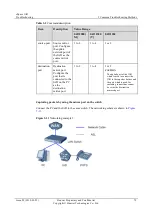
fixation nut firmly, as shown in
. The cross-sectional area of the PGND cable must
not be less than 4 mm
2
, and the PGND cable should be as short as possible. Do not wind the
cable.

