l
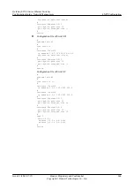
Configuration file of Switch D
#
sysname SwitchD
#
vlan batch 10
#
interface Vlanif10
ip address 3.0.1.32 255.255.255.0
ntp-service broadcast-client
#
interface Ethernet0/0/1
port hybrid pvid vlan 10
port hybrid untagged vlan 10
#
ntp-service authentication enable
ntp-service authentication-keyid 16 authentication-mode md5 %@ENC;8HX
\#Q=^Q`MAF4<1!!
ntp-service reliable authentication-keyid 16
#
return
l
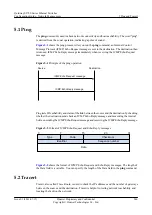
Configuration file of Switch F
#
sysname SwitchF
#
vlan batch 10 20
#
interface Vlanif10
ip address 3.0.1.2 255.255.255.0
#
interface Vlanif20
ip address 1.0.1.2 255.255.255.0
#
interface Ethernet0/0/1
port hybrid pvid vlan 20
port hybrid untagged vlan 20
#
interface Ethernet0/0/2
port hybrid pvid vlan 10
port hybrid untagged vlan 10
#
ospf 1
area 0.0.0.0
network 1.0.1.0 0.0.0.255
network 3.0.1.0 0.0.0.255
#
return
4.6.4 Example for Configuring the Common NTP Multicast Mode
Networking Requirements
l
Switch C and Switch D are on the same network segment; Switch A is on another network
segment; Switch F connects the two network segments.
l
As the NTP multicast server, Switch C uses the local clock as the NTP master clock, which
is a stratum-2 clock. Switch C sends multicast packets through VLANIF 10, namely,
Ethernet0/0/1.
l
Switch D uses VLANIF 10, namely, Ethernet0/0/1, to listen to the multicast packets.
l
Switch A uses VLANIF 20, namely, Ethernet0/0/1, to listen to the multicast packets.
Quidway S2700 Series Ethernet Switches
Configuration Guide - Network Management
4 NTP Configuration
Issue 01 (2011-07-15)
Huawei Proprietary and Confidential
Copyright © Huawei Technologies Co., Ltd.
240


