9
LP-04 REV. 4.15.14
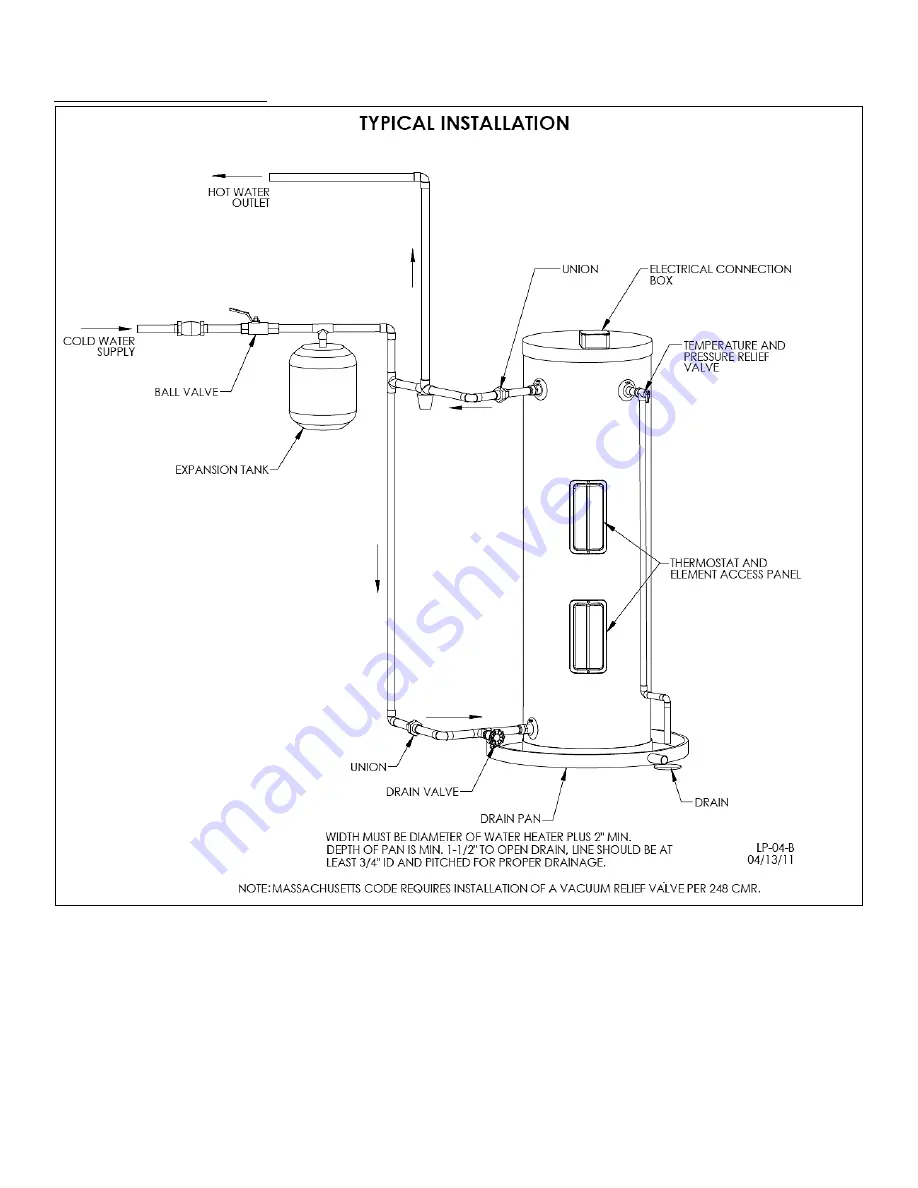
F. INSTALLATION DIAGRAMS
Figure 3
– Piping Detail - NOTE: Drawing is meant only to demonstrate system piping concept. The installer is responsible for
all equipment and detailing required by local codes.
Страница 1: ...oduct contains chemicals known to the State of California to cause cancer birth defects or other reproductive harm NOTICE HTP reserves the right to make product changes or updates without notice and w...
Страница 2: ...rety before beginning any work Installation should be made in accordance with the regulations of the Authority Having Jurisdiction local code authorities and utility companies which pertain to this ty...
Страница 3: ...ble materials 0 top bottom sides and back Heater must have room for service 24 front and 6 sides are minimum recommended service clearances A combustible door or removable panel is acceptable front cl...
Страница 4: ...CA 95814 or you may call 916 324 5315 or ask a water heater dealer However applicable local codes shall govern installation For residential water heaters of a capacity greater than 52 gallons consult...
Страница 5: ...22 27 19 41 EV 30 30 4500 240 4 34 39 19 55 EV 30LB 30 4500 240 4 21 28 23 65 EV 45LB 45 4500 240 4 34 42 23 86 EV 50 50 4500 240 4 56 63 19 1 90 EV 80 80 4500 240 5 64 72 23 1 132 Table 1 Specificat...
Страница 6: ...result in substantial property damage severe personal injury or death 2 Check for nearby connections to System water piping Electrical power Choose a location for the water heater as centralized to th...
Страница 7: ...testing laboratory that maintains periodic inspection of production of listed equipment and materials Install the T P valve into the opening provided and marked for this purpose on the water heater so...
Страница 8: ...cold and hot water in branch supply lines Such valves are available from your local plumbing supplier Table 2 details the relationship of water temperature and time with regard to scald injury and ma...
Страница 9: ...REV 4 15 14 F INSTALLATION DIAGRAMS Figure 3 Piping Detail NOTE Drawing is meant only to demonstrate system piping concept The installer is responsible for all equipment and detailing required by loca...
Страница 10: ...V 4 15 14 Figure 4 Mobile Home and Point of Use Piping Detail NOTE Drawing is meant only to demonstrate system piping concept The installer is responsible for all equipment and detailing required by l...
Страница 11: ...the 120 volt model the white wire must be connected to the neutral leg 240V electrical installation should be done by a qualified licensed electrician or by your local electric utility All wiring mus...
Страница 12: ...protective cover should NOT be removed Set temperature indicator to desired temperature Replace insulation and the black access cover Turn on power to the heater See below for Thermostat adjustment E...
Страница 13: ...Screw the element clockwise into tank and tighten with the 1 socket wrench Be sure O ring seats properly STEP 6 Refill the tank with cold water STEP 7 Pressure check the tank for leaks around element...
Страница 14: ...for assistance Check the area around the water heater for flammable liquids or combustible materials If any are found remove from the area Vacation Extended Shut Off Periods During extended mild or w...
Страница 15: ...at 4 Manual Reset High Limit Switch ECO open a Thermostat s defective b Thermostat out of calibration c Heat build up due to loose wires d Defective High Limit Switch ECO 1 Turn switch ON 2 Rewire per...
Страница 16: ...LECTRIC ELEMENT W O RING EV 6 EV 20 1 2 6060P 187 ELECTRICAL BOX COVER 2 3 TP1500 3 4 T P VALVE 100XL 8 1 4 6060P 633 THERMODISC MOUNTING CLIP 2 5 TD1015 UPPER THERMOSTAT CONTROL 1 6 6060P 1009 THERMO...
Страница 17: ...17 LP 04 REV 4 15 14 NOTES...
Страница 18: ...nstallation Address Date of Installation Installer s Code Name Product Serial Number s Comments Installer s Phone Number Signed by Installer Signed by Customer IMPORTANT Customer Please only sign afte...