background image

 7 

If assembling an SXRC-1V (single-level stand or amp stand) go to Step 10. If not, 
continue with next step. 

 
Step  5.   

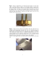
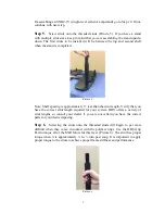
Screw  struts  onto  the  threaded  studs  (Picture  5).  If  you  have  a  stand 

with multiple strut sizes, keep in mind that you are assembling the stand upside-
down.  The  first  struts  to  be  installed  will  be  between  the  top  and  second  shelf 
when the stand is completed.  


Picture 5 


Note: Shelf spacing is approximately 3” less than the strut length. Verify that you 
have  the  correct  strut  length  required  for  your  system.  HRS  offers  a  variety  of 
strut  lengths  so  consult  your  dealer  if  you  are  not  certain  you  have  the  correct 
parts for your desired spacing.  
 

Step  6.   

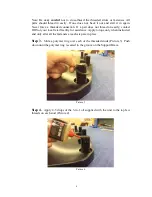
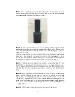
Screwing  the  struts  onto  the  threaded  studs  will  begin  to  get  more 

difficult  when  they  come  in  contact  with  the  polymer  rings.  Use  the  HRS  Grip 
Pad to torque all of the SXR Struts for this layer (Picture 6). The strut has proper 
torque  when  it  is  approximately 

¼

  to 

½

  turn  past  snug.  It  is  important  to  apply 

proper torque to the struts to achieve proper frame stiffness and performance. 


Picture 6 

Содержание SXRC AUDIO STAND

Страница 1: ...SXRC AUDIO STAND A Low Noise Floor Is Fundamental ...

Страница 2: ...duce the harmful effects of air borne noise and structural resonance on your components Please read this manual completely prior to assembly and use of your SXRC Audio Stand It contains instructions necessary for proper assembly use and care of this system Proper care of your SXRC Audio Stand will ensure optimum performance and an aesthetically appealing system All HRS products are manufactured in...

Страница 3: ...C Audio Stand frame to its final location prior to loading shelves and components Moving the SXRC Audio Stand frame with the isolation bases installed with or without equipment can permanently damage the frame system or cause the shelves to fall out of the rack resulting in potential damage or injury Always take the time to remove all of the equipment and shelves to relocate the SXRC Audio Stand D...

Страница 4: ...y Hardware Remove all the contents from all the boxes marked with SXRC model number Place all the hardware on a table adjacent to your selected work surface and remove all the wrapping material Be careful not to drop or allow the anodized aluminum parts to contact each other as they may scratch the surface Do not stack the parts on top of each other once they are removed from the protective packag...

Страница 5: ...mbers face the same direction Picture 1 Step 2 Using the 5 32 ratchet wrench supplied with unit attach the Cross Members to the Support Brace with the 1 4 20 x 3 4 flat head cap screws supplied with the unit Picture 2 Before tightening screws fully be sure that the Cross Member and Support Brace are completely perpendicular to each other minor adjustments can be made prior to tightening the bolts ...

Страница 6: ...y contact HRS or your local retail facility for assistance Apply torque only when instructed and only after all the fasteners at each step are in place Step 3 Slide a polymer ring over each of the threaded studs Picture 3 Push down until the polymer ring is seated in the groove on the Support Brace Picture 3 Step 4 Apply 4 5 drops of the 3 in 1 oil supplied with the unit to the top few threads on ...

Страница 7: ...an the strut length Verify that you have the correct strut length required for your system HRS offers a variety of strut lengths so consult your dealer if you are not certain you have the correct parts for your desired spacing Step 6 Screwing the struts onto the threaded studs will begin to get more difficult when they come in contact with the polymer rings Use the HRS Grip Pad to torque all of th...

Страница 8: ... must be loosened 1 4 turn before proceeding to Step 9 Step 9 Carefully place the Support Cross Member subassembly onto the struts of the SXRC by placing each strut through one hole of the Support Braces Make sure the HRS logos on all of the Cross Members face the same direction Also make sure that each strut is properly seated into a countersunk hole of the Support Brace Step 10 Fully tighten the...

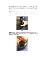
Страница 9: ...n past snug Step 12 Make sure there is a Polymer Ring over each of the exposed threads and screw a Locking Nut onto each one Tighten the Locking Nuts by hand at first then torque them using the custom nylon wrench another turn past snug Picture 8 Picture 8 Step 13 Screw Washers onto the threads over the Locking Nuts Picture 9 Screw the Washers down only until they contact the Locking Nut Do not pu...

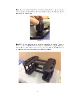
Страница 10: ...ers Do not over torque the Stand Points Picture 10 Step 15 At this point the SXRC Frame is completely assembled Picture 11 shows a completed SXRC 1921 2V Flip the SXRC Frame upright Move the frame to the exact final location for use in your system The front of the frame is the side from which the HRS logos can be read right side up Picture 11 ...

Страница 11: ...at the additional travel is achieved without violating the 3 full thread minimum engagement requirement Now bring down the rest of the Stand Points so that they are in contact with the floor After the stand frame is level hold the Stand Points with one hand and screw the Washer with your other hand down until it touches the top of the Stand Point Torque the Washer against the Stand Point as much a...

Страница 12: ... have the correct load range for a component please contact Harmonic Resolution Systems or your local certified retail location to arrange to have this corrected Load the Isolation Bases into the SXRC frame with the HRS logo facing the front of the rack system Picture 12 shows this in an SXR 3V system Be sure that the isolation base shelf feet are located securely in the pocket of the SXRC Support...

Страница 13: ... base slightly when you squeeze your fingers together If there is no compliance remove the isolation base and component to verify the load range of the isolation base is correctly matched with the component The load range of each isolation base is identified by the colored sticker on the back of the base see the isolation base manual for instructions Please consult with your authorized Harmonic Re...

Страница 14: ...se will cause permanent damage to the assembly Clean the metallic parts of the isolation base and SXRC Audio Stand using a lint free soft non abrasive cloth Use a damp cloth with a mild soap or Pledge Surface Cleaner if required Do not use abrasive cleaners or solvents to clean the SXRC frame or isolation base as they will damage the quality of finish Solvents and solvent based cleaners will attac...

Страница 15: ...ported or the defect is due to the product being repaired or tampered with or modified by anyone other than Harmonic Resolution Systems The product must be packed and returned to Harmonic Resolution Systems by the customer at his or her sole expense A written description of the defect and a photocopy of the original purchase receipt must accompany a returned product This receipt must clearly list ...

Страница 16: ... accept the return Units shipped to Harmonic Resolution Systems without a visible RA Number on the exterior of the shipping container s are subject to be returned to the sender freight collect Units to be repaired by Harmonic Resolution Systems must be sent shipping and insurance prepaid by the original purchaser in the original packaging material A returned product should be accompanied by a writ...

Страница 17: ...States of America by skilled craftsmen using only the finest materials and our personal dedication to the highest workmanship standards HARMONIC RESOLUTION SYSTEMS INC 2495 Main Street Suite 227 Buffalo NY 14214 Telephone 716 873 1437 Web www AVisolation com E mail sales AVisolation com ...

Отзывы: