


Remove the server from the rack
Remove the server from the rack
Prerequisites
Prerequisites
Get help to lift and stabilize the server during removal from the rack. If the
If the server
server is installed higher than chest level, an additional
is installed higher than chest level, an additional
person might be required to help remove the
person might be required to help remove the server
server:: one person to support the server weight, and the other to slide the server out
of the rack.
Before you perform this procedure, review the:
A fully populated server is heavy. Hewlett Packard Enterprise recommends removing the external server components before
removing the server from the rack.
Before you perform this procedure, make sure that you have a T-25 Torx screwdriver available.
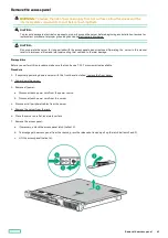
Procedure
Procedure
1. If physically powering down a server with the front bezel installed, remove the front bezel .
3. Remove all power:
a. Disconnect each power cord from the power source.
b. Disconnect each power cord from the server.
4. Disconnect all peripheral cables from the server.
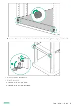
5. Extend the server from the rack, do one of the following:
WARNING:
WARNING: To reduce the risk of personal injury or equipment damage, be sure that the rack
is adequately stabilized before extending a component from the rack.
For a server that has thumbscrew ears, do the following:
a. Loosen the captive thumbscrews (callout 1).
b. Slide the server out of the rack until the rail-release latches are engaged (callout 2).
For a server that has quick-release chassis ears , do the following:
a. Open the chassis ear latch (callout 1).
Remove the server from the rack
39
Содержание ProLiant DL20 Gen10 Plus
Страница 20: ...DIMM slot location The arrow points to the front of the server DIMM slot location 20 ...
Страница 30: ...Fan numbering Fan numbering 30 ...
Страница 100: ...Installing an optical drive in the LFF drive chassis 100 ...
Страница 154: ...Cabling This chapter includes cabling guidelines and diagrams for internal component cabling Cabling 154 ...
Страница 169: ...Energy pack cabling Energy pack cabling 169 ...
Страница 174: ...M 2 SATA SSD add in card cabling 174 ...
Страница 176: ...Fan cabling Color Description Orange Fan 1 cable Blue Fan 2 cable Gold Fan 3 cable Fan cabling 176 ...
Страница 177: ...Chassis intrusion detection switch cabling Chassis intrusion detection switch cabling 177 ...
Страница 178: ...Serial port cabling Serial port cabling 178 ...
Страница 180: ...Power supply cabling 180 ...
Страница 185: ...Troubleshooting NMI functionality Troubleshooting resources Troubleshooting 185 ...
Страница 196: ...Ukraine RoHS material content declaration Ukraine RoHS material content declaration 196 ...


