HP StorageWorks Modular Smart Array 500 System Скачать руководство пользователя страница 22

Removal and Replacement Procedures 

2-14


HP StorageWorks Modular Smart Array 500 System Maintenance and Service Guide 


HP CONFIDENTIAL

 Codename: Aurora Part Number: 251850-004 Last Saved On: 9/19/03 10:57 AM 


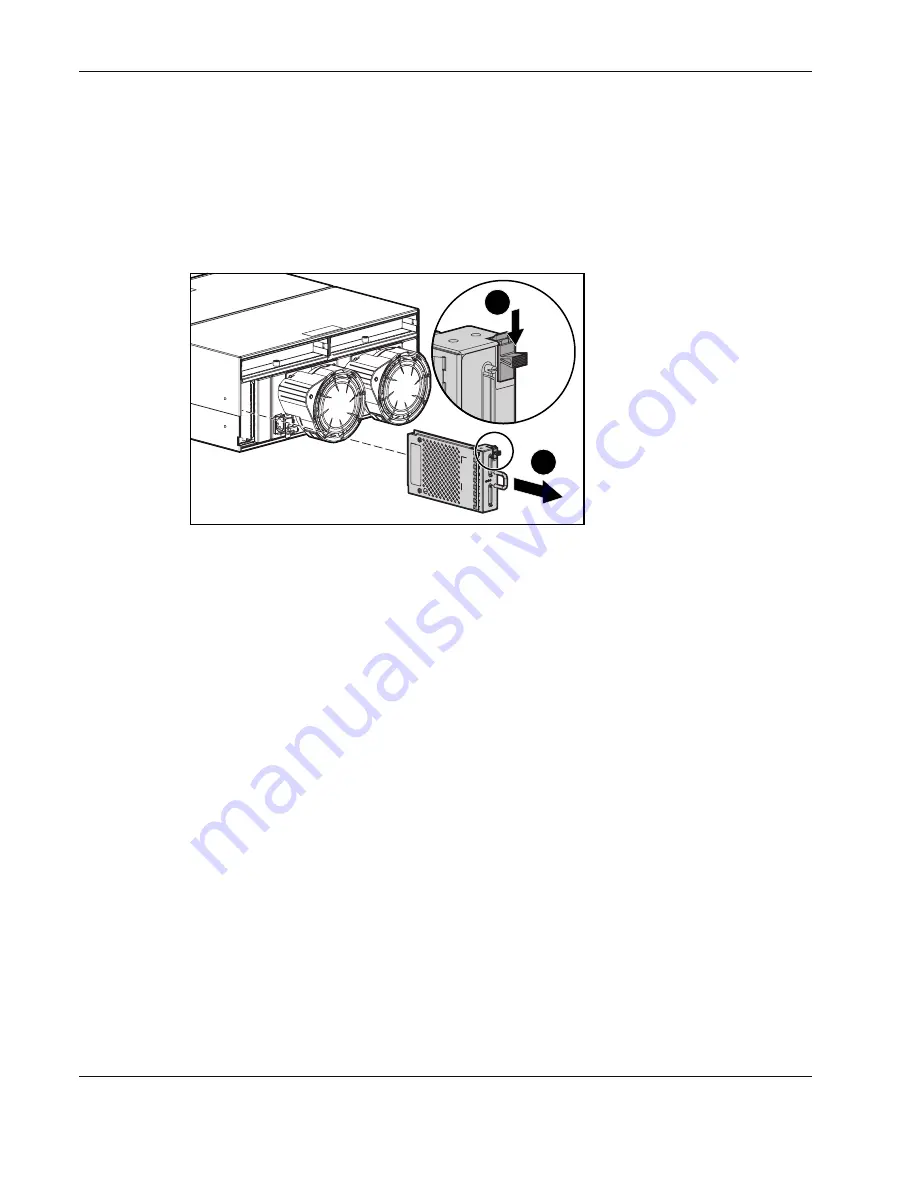
2-Port and 4-Port Shared Storage Modules 

To remove the component: 

1.  Power down the system. Refer to “System Power Down” in this chapter. 

2.  Disconnect the SCSI cabling connected to the 2-Port Ultra3 SCSI I/O module. 

3. Remove 

the 

module. 

2

1


To replace the component, reverse the removal procedure. 

If you are replacing a failed 2-Port Shared Storage Module with a 4-Port Shared Storage 
Module, refer to the 

4-Port Shared Storage Module Installation Instructions

 that ship with 

the option. 

Содержание StorageWorks Modular Smart Array 500 System

Страница 1: ...ora Part Number 251850 004 Last Saved On 9 19 03 10 52 AM HP StorageWorks Modular Smart Array 500 System Maintenance and Service Guide formerly Smart Array Cluster Storage System October 2003 Fourth Edition Part Number 251850 004 ...

Страница 2: ...hnical or editorial errors or omissions contained herein The information in this document is provided as is without warranty of any kind and is subject to change without notice The warranties for HP products are set forth in the express limited warranty statements accompanying such products Nothing herein should be construed as constituting an additional warranty HP StorageWorks Modular Smart Arra...

Страница 3: ...harge 2 1 Rack Warnings and Cautions 2 2 Device Warnings and Cautions 2 2 Weight Warning 2 3 System Power Down 2 4 Hard Drive Blank 2 4 Hot Plug SCSI Hard Drive 2 5 Universal Hot Plug Tape Drive 2 7 Bezel Blank 2 8 HP StorageWorks Modular Smart Array 500 Controller 2 9 Battery Backed Cache Module 2 10 Blower 2 11 Hot Plug Power Supply 2 12 2 Port and 4 Port Shared Storage Modules 2 14 Interconnect...

Страница 4: ...LEDs 4 3 2 Port Shared Storage Module Components 4 4 2 Port Shared Storage Module LEDs 4 5 4 Port Shared Storage Module Components 4 6 4 Port Shared Storage Module LEDs 4 7 Controller Components 4 8 Controller Display 4 8 Controller LEDs 4 9 SCSI IDs 4 11 Hot Plug SCSI Hard Drive LEDs 4 12 Hot Plug SCSI Hard Drive LED Combinations 4 12 Chapter 5 Specifications System Unit Specification 5 1 Memory ...

Страница 5: ...to repair this equipment All troubleshooting and repair procedures are detailed to allow only subassembly module level repair Because of the complexity of the individual boards and subassemblies no one should attempt to make repairs at the component level or to make modifications to any printed wiring board Improper repairs can create a safety hazard WARNING To reduce the risk of personal injury f...

Страница 6: ...ion sources are available HP StorageWorks Modular Smart Array 500 System User Guide HP StorageWorks Modular Smart Array 500 System Hardware Configuration and Installation Poster HP StorageWorks Modular Smart Array 500 Controller Installation Instructions HP DC Power Supply Option Installation Instructions HP 4 Port Shared Storage Module Option Installation Instructions Operating System and Drivers...

Страница 7: ...ar Smart Array 500 System Maintenance and Service Guide 1 1 HP CONFIDENTIAL Codename Aurora Part Number 251850 004 Last Saved On 9 19 03 10 55 AM 1 Illustrated Parts Catalog Mechanical and System Components 6 3 5 2 8 7 1 4 ...

Страница 8: ...s 6 2 Port Shared Storage Module for HP StorageWorks Modular Smart Array 500 system 229205 001 7 Controller 229202 001 8 Power button LED assembly 229201 001 9 Cache module DIMM SDRAM 128 MB with battery 171387 001 Miscellaneous 10 AC power cord 187335 001 11 Return kit 249670 001 Options 12 4 Port Shared Storage Module for MSA500 system 300867 001 13 DC power supply 48 V 243791 001 14 Cache modul...

Страница 9: ...ng the system be aware of the precautions you need to follow when setting up the system or handling parts A discharge of static electricity from a finger or other conductor may damage system boards or other static sensitive devices This type of damage may reduce the life expectancy of the device To prevent electrostatic damage Avoid hand contact by transporting and storing products in static safe ...

Страница 10: ...ons Fully extend the bottom stabilizers on the equipment Be sure that the equipment is properly supported braced when installing options and boards Be sure that the rack is adequately stabilized before extending a component outside the rack Extend only one component at a time A rack may become unstable if more than one component is extended for any reason Do not attempt to move a fully loaded equi...

Страница 11: ...ectrical outlet that is easily accessible at all times Unplug the power cord from the power supply to disconnect power to the equipment Do not route the power cord where it can be walked on or pinched by items placed against it Pay particular attention to the plug electrical outlet and the point where the cord extends from the system Do not use conductive tools that could bridge live parts Remove ...

Страница 12: ...cuitry remain active until AC power is removed IMPORTANT If installing a hot plug device it is not necessary to power down the system To power down the system 1 Power down any attached servers Refer to the server documentation 2 Press the Power On Standby button Wait for the system power LED to go from green to off 3 Disconnect the power cords Hard Drive Blank CAUTION Always populate drive bays wi...

Страница 13: ...ion Follow these additional guidelines when replacing drives Never remove more than one drive at a time or two drives if you are using Advanced Data Guarding When you replace a drive the controller uses data from the other drives in the array to reconstruct data on the replacement drive If you remove more than one drive a complete data set is not available to reconstruct data on the replacement dr...

Страница 14: ...s all bays are populated with either a component or a blank 2 Remove the failed drive 1 2 3 To replace a hot plug SCSI hard drive 1 Slide the drive into the bay until it locks into place 2 Close the lever CAUTION Data loss can occur if the drive is not firmly seated 3 Be sure that the drive LEDs illuminate one at a time and then turn off together to indicate that the system has recognized the new ...

Страница 15: ...mal damage do not operate the system unless all bays are populated with either a component or a blank CAUTION Installation of the tape drive height converter is permanent Attempting to remove the converter after installation voids the tape drive warranty 1 2 To replace the Universal Hot Plug Tape drive 1 Install a new tape drive height converter on the replacement tape drive 2 Slide the tape drive...

Страница 16: ... 9 19 03 10 57 AM Bezel Blank To remove the component CAUTION Always populate bays with either a component or blank Proper airflow can only be maintained when the bays are populated Operating the system with unpopulated bays can lead to improper cooling and thermal damage 1 2 3 To replace the bezel blank 1 Slide the bezel blank into the bay until it locks into place 2 Close the lever ...

Страница 17: ...Failure to migrate the cache to a new controller and flush the data can result in loss of the data that is written in the cache but was unable to be written to the hard drives before controller failure To remove the component 1 2 To restore the data 1 Remove the cache modules from the failed controller Refer to Battery Backed Cache Module in this chapter 2 Install the cache modules in the new cont...

Страница 18: ...ng step 2 Refer to System Power Down in this chapter If the system has redundant controllers and the replacement cache is a different capacity than the failed cache power down the system before performing step 2 If the system has redundant controllers and the replacement cache is the same capacity as the failed cache proceed with step 2 2 Remove the controller Refer to HP StorageWorks Modular Smar...

Страница 19: ...so that removing a blower does not adversely affect system performance However do not remove a blower until the replacement blower is available 1 1 2 To replace the blower 1 Align the guidepost on the blower with the connector on the power supply CAUTION Do not press on the center section of the blower because this action can damage the blades Press only on the outer edge of the blower 2 Slide the...

Страница 20: ...upply is intended only for installation in HP equipment located in a restricted access location This power supply is not intended for direct connection to the DC supply branch circuit It should be connected to a power distribution unit PDU that provides an independent overcurrent protected output for each DC power supply Each output overcurrent protected device in the PDU must be suitable for inte...

Страница 21: ...ower cord from the power supply 2 Remove the blower Refer to Blower in this chapter 3 Remove the power supply 2 1 To replace the power supply 1 Lift the locking latch 2 Slide the power supply into the bay until it locks into place 3 Install the blower on the power supply 4 Connect the power cord If you are replacing AC power supplies with DC power supplies refer to the DC Power Supply Option Insta...

Страница 22: ...ules To remove the component 1 Power down the system Refer to System Power Down in this chapter 2 Disconnect the SCSI cabling connected to the 2 Port Ultra3 SCSI I O module 3 Remove the module 2 1 To replace the component reverse the removal procedure If you are replacing a failed 2 Port Shared Storage Module with a 4 Port Shared Storage Module refer to the 4 Port Shared Storage Module Installatio...

Страница 23: ...ber 251850 004 Last Saved On 9 19 03 10 57 AM Interconnect Blank To remove the component CAUTION Always populate interconnect bays with a blank Proper airflow can only be maintained when the bays are populated Operating the system with unpopulated bays can lead to improper cooling and thermal damage 2 1 To replace the component reverse the removal procedure ...

Страница 24: ...e component 1 Power down the system Refer to System Power Down in this chapter 2 Remove the hot plug SCSI hard drives in bays 10 through 14 Refer to Hot Plug SCSI Hard Drive in this chapter IMPORTANT To press the plastic latches behind the front bezel you may choose to use a flat head screwdriver 3 Remove the power button LED assembly 2 1 1 To replace the component slide the power button LED assem...

Страница 25: ...al Hot Plug Tape Drive in this chapter 5 Remove the bezel blank Refer to Bezel Blank in this chapter 6 Remove the controllers Refer to HP StorageWorks Modular Smart Array 500 Controller in this chapter 7 Remove the power supplies Refer to Hot Plug Power Supply in this chapter 8 Remove the 2 Port or 4 Port Shared Storage module Refer to 2 Port and 4 Port Shared Storage Modules in this chapter 9 Rem...

Страница 26: ... Insight Manager 7 This Web based application enables system administrators to accomplish normal administrative tasks from any remote location using a Web browser Insight Manager 7 provides device management capabilities that consolidate and integrate management data from HP and third party devices Insight Management Agents These agents enable easy manageability of the server through Insight Manag...

Страница 27: ... to a file for analysis In most cases ADU provides sufficient information for troubleshooting procedures To obtain ADU download the utility from the HP website www hp com Array Configuration Utility ACU Version 6 0 or later is a browser based utility with the following features Supports online array capacity expansion logical drive capacity extension assignment of online spares and RAID or stripe ...

Страница 28: ...lled CPQONLIN is a NetWare Loadable Module NLM for configuring drive arrays without shutting down the server CPQONLIN also provides information about the status of drives attached to the MSA500 controller It indicates drive failure expansion or waiting for expansion or rebuild queued For more NetWare Online Array Configuration Utility information refer to the HP StorageWorks Modular Smart Array 50...

Страница 29: ...4 Component Identification Front Panel Components 1 3 4 2 7 6 5 Table 4 1 Front Panel Components Item Description 1 Bezel blank bay for optional redundant controller 2 Service port for HP service technicians only 3 Hot plug MSA500 controller 4 Controller display 5 Power On Standby button 6 Enclosure LEDs refer to Table 4 2 7 Hot plug SCSI hard drive bays with blanks ...

Страница 30: ... operating normally Green Off Shared storage module is not operating normally 2 System power Green System power is On Off System is in standby mode or power is removed from the system 3 Fault Amber Fault detected in a subsystem Off No faults detected IMPORTANT The Power On Standby button does not remove all power from the system The Standby mode removes power from most of the electronics and the d...

Страница 31: ...le 4 3 Rear Panel Components Item Description 1 Interconnect blanks Required for proper airflow 2 Power supply blower assemblies 3 AC power connectors 4 2 Port Shared Storage Module Power Supply Blower Assembly LEDs The power supply blower assembly LEDs have the following functions Green The power supply is receiving power and the blower is operating normally Off No power is present the power supp...

Страница 32: ...enance and Service Guide HP CONFIDENTIAL Codename Aurora Part Number 251850 004 Last Saved On 9 19 03 11 00 AM 2 Port Shared Storage Module Components 1 2 Table 4 4 2 Port Shared Storage Module Components Item Connector Description Bus 1 SCSI port connector A 2 SCSI port connector B ...

Страница 33: ...HP CONFIDENTIAL Codename Aurora Part Number 251850 004 Last Saved On 9 19 03 11 00 AM 2 Port Shared Storage Module LEDs 1 2 3 Table 4 5 2 Port Shared Storage Module LEDs Item LED Description Status 1 Power Green Power on Off Power off 2 SCSI host port A 3 SCSI host port B Flashing green On Activity Off Off ...

Страница 34: ...NFIDENTIAL Codename Aurora Part Number 251850 004 Last Saved On 9 19 03 11 00 AM 4 Port Shared Storage Module Components 2 1 4 3 Table 4 6 4 Port Shared Storage Module Components Item Connector Description Bus 1 SCSI port connector A1 2 SCSI port connector A2 A 3 SCSI port connector B1 4 SCSI port connector B2 B ...

Страница 35: ...ename Aurora Part Number 251850 004 Last Saved On 9 19 03 11 00 AM 4 Port Shared Storage Module LEDs 1 2 3 Table 4 7 4 Port Shared Storage Module LEDs Item LED Description Status 1 Power Green Power on Off Power off 2 SCSI host port A connectors 1 and 2 3 SCSI host port B connectors 1 and 2 Flashing green On Activity Off Off ...

Страница 36: ...ENTIAL Codename Aurora Part Number 251850 004 Last Saved On 9 19 03 11 00 AM Controller Components Controller Display Each MSA500 controller has an LCD display for informational and error messages 1 2 3 4 5 Table 4 8 Controller Display Item Description 1 Display 2 Left button 3 Up button 4 Right button 5 Down button ...

Страница 37: ...ation Green Notify On Event command active Off No Notify On Event command active 7 Host port B notification Green Notify On Event command active Off No Notify On Event command active 8 Idle heartbeat Controller is idle and functioning 9 Active Standby Green Controller is active Off Controller is in standby 10 DMA activity Green DMA transfers are active Off No DMA transfers 11 Logical I O activity ...

Страница 38: ...ed Item LED Description Status 14 Cache activity Green Cache activity Off No cache activity Flashing green Cache transfer pending 15 Drive failure Green An array configured drive has failed Off No drive failures 16 Active redundancy Green Controllers are operating with redundancy Off No redundancy 17 Fault Amber Error message received by controller display Off No error message received or no error...

Страница 39: ...em Maintenance and Service Guide 4 11 HP CONFIDENTIAL Codename Aurora Part Number 251850 004 Last Saved On 9 19 03 11 00 AM SCSI IDs 14 7 6 5 4 3 2 1 8 9 10 11 12 13 Table 4 10 SCSI IDs Bay SCSI ID Bus Port 1 0 2 1 3 2 4 3 5 4 6 5 7 8 0 8 0 9 1 10 2 11 3 12 4 13 5 14 8 1 ...

Страница 40: ...o not remove the drive Removing a drive during this process can cause data loss in non fault tolerant configurations The drive is a replacement drive and is being rebuilt or If all online LEDs in a drive array are flashing an expansion is occurring Off Off On OK to replace the drive online The drive has failed and has been placed offline Off on or flashing On Off Do not remove the drive Removing a...

Страница 41: ...equency 50 to 60 Hz Rated input current 7 35 A Max Input power max 641 W Power supply specifications Rated steady state power 499 W Maximum peak power 681 W Heat dissipation max 2187 Btu hr Acoustic noise LWAdc bels and LpAm dBA Idle 6 9 and 53 Fixed disk random writes 7 3 and 54 Temperature range Operating 10 to 35 C 50 to 95 F derated 1 C per 304 8 m 1 8 F per 1000 ft of elevation to 3 048 m 10 ...

Страница 42: ...perating 10 to 90 Nonoperating up to 95 Maximum wet bulb temperature Long term storage 29 C 84 2 F Short term storage 30 C 86 F Memory Table 5 2 SDRAM DIMM Specifications Specification Value Speed 100 MHz minimum Width 80 bits Note Use only HP battery backed cache modules 2 Port and 4 Port Shared Storage Modules Table 5 3 2 Port and 4 Port Shared Storage Module Specifications Specification Value H...

Страница 43: ...tion Value Voltage Nominal input voltage 48 or 48 VDC Maximum input voltage 75 VDC Operating voltage range 36 to 72 VDC Ripple Noise 100 mV PARD Overshoot Must remain within regulation limits during startup or shutdown Current Max steady state input current 13 2 A In rush current 70 A Input over current Customer must provide fusing for facility DC feeds that protect the system from catastrophic ov...

Страница 44: ... B backplane removing 2 17 replacing 2 17 battery backed cache module removing 2 10 replacing 2 10 spare part number 1 2 bays SCSI hard drive 4 1 bezel blank location 4 1 removing 2 8 replacing 2 8 spare part number 1 2 blowers LEDs 4 3 location 4 3 removing 2 11 replacing 2 11 spare part number 1 2 C cache module See battery backed cache module CDs Documentation 3 2 SmartStart 3 2 chassis replaci...

Страница 45: ...y 4 12 drive online 4 12 EMU heartbeat 4 2 enclosure 4 1 4 2 fault 4 10 4 12 fault enclosure 4 2 hot plug SCSI hard drives 4 12 power supply blower assembly 4 3 system power 4 2 M mechanical components 1 2 modules See 2 Port Shared Storage Module 4 Port Shared Storage Module battery backed cache module M Series Rack Rail option spare part number 1 2 P ports LEDs 4 5 4 7 service 4 1 power button LE...

Страница 46: ...d Storage Module SmartStart CD 2 1 3 2 spare part numbers 2 Port Shared Storage Module 1 2 4 Port Shared Storage Module 1 2 AC power cord 1 2 array controller 1 2 battery backed cache module 1 2 bezel blank 1 2 blower 1 2 chassis 1 2 hot plug SCSI hard drives 1 2 interconnect blank 1 2 M Series Rack Rail option 1 2 power button LED assembly 1 2 power supplies 1 2 return kit 1 2 tape drives 1 2 Sur...

Отзывы: