Removal and replacement procedures 35
7.
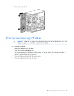
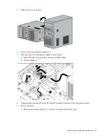
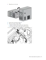
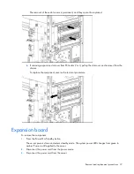
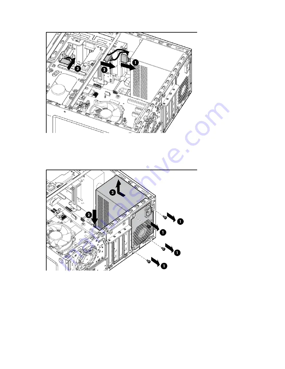
Disconnect the power supply cables from all installed drives.
8.
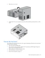
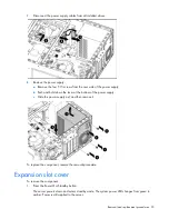
Remove the power supply:
a.
Remove the four T-15 screws from the rear side of the power supply.
b.
Push and hold down the lever at the bottom of the power supply.
c.
Slide the power supply out, and then remove it.
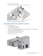
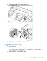
To replace the component, reverse the removal procedure.
Expansion slot cover
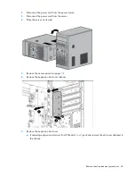
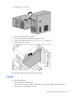
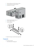
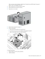
To remove the component:
1.
Press the Power On/Standby button.
The server powers down and enters standby mode. The system power LED changes from green to
amber. Power is still applied to the server.
Содержание ProLiant ML10
Страница 12: ...Customer self repair 12 ...
Страница 13: ...Customer self repair 13 ...
Страница 14: ...Customer self repair 14 ...
Страница 17: ...Illustrated parts catalog 17 System components ...
Страница 62: ...Component identification 62 Fan locations Item Description 1 Rear system fan 2 Processor heatsink fan assembly ...
Страница 65: ...Cabling 65 Ambient temperature sensor cabling Fan cabling System fan ...
Страница 70: ...Acronyms and abbreviations 70 SFF small form factor SIM Systems Insight Manager USB universal serial bus ...

