


Removal and replacement procedures 90
System fan
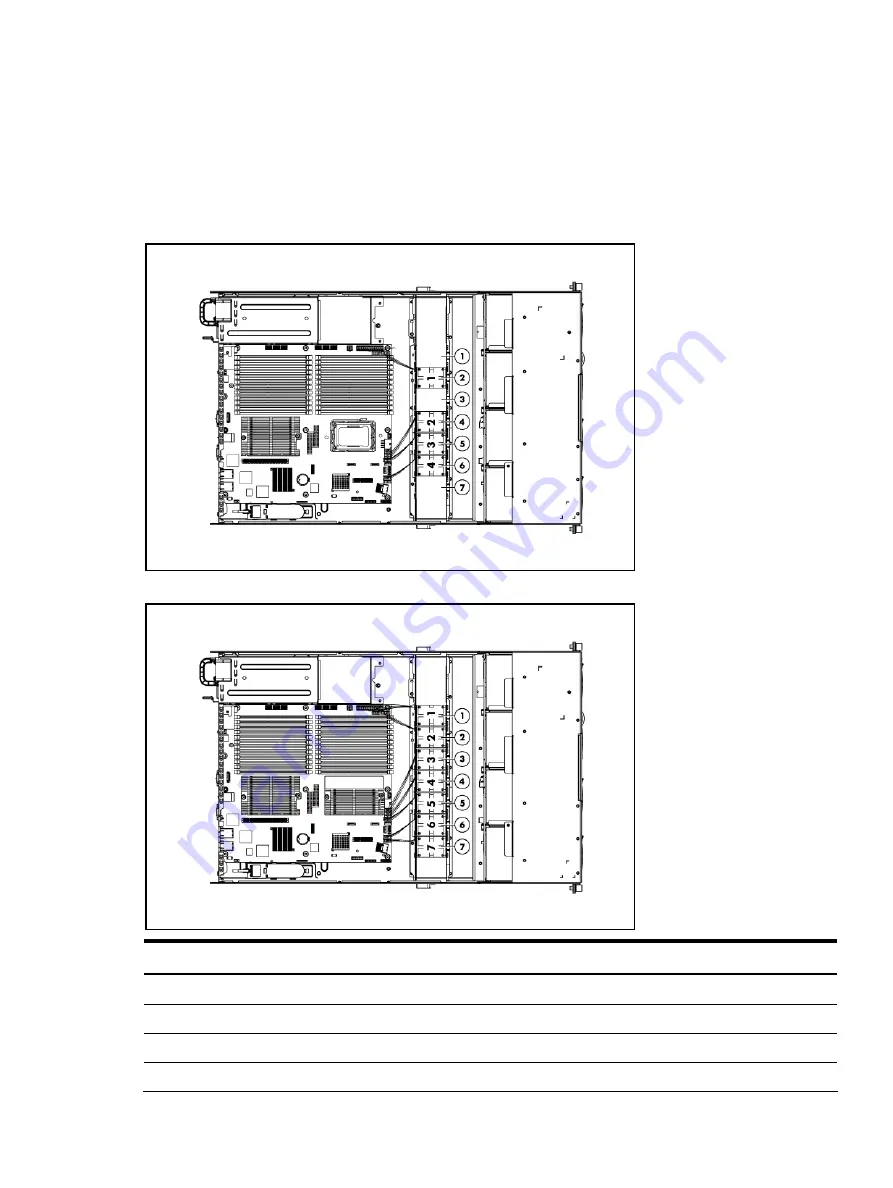
The server can support up to seven system fans located on the center wall of the chassis. When the
server is installed with one processor, the system fans should be installed in the 2
nd
, 4
th
, 5
th
and 6
th
system fan locations. When the server is installed with two processors, the redundant fan functions are
supported by the system fan 1, system fan 3, and system fan 7 when installed.
Figure 86
System Fan Connections for One Processor Configuration
Figure 87
System Fan Connections for Two Processors Configuration with N+1 Redundancy Fan
Device number
Connector
System fan 1
J61 on the system board
System fan 2
J62 on the system board
System fan 3
J63 on the system board
System fan 4
J64 on the system board
Содержание ProLiant DL165 G7
Страница 12: ...Customer self repair 12 ...
Страница 13: ...Customer self repair 13 ...
Страница 14: ...Customer self repair 14 ...
Страница 15: ...Customer self repair 15 ...
Страница 20: ...Illustrated parts catalog 20 ...
Страница 54: ...Removal and replacement procedures 54 Figure 31 Reinstalling the Backplane 3 Install all cables ...
Страница 60: ...Removal and replacement procedures 60 7 Engage the load lever ...
Страница 92: ...Removal and replacement procedures 92 Figure 89 Reinstalling the System Fan ...


