HP ProLiant DL160se - G6 Server Скачать руководство пользователя страница 41


Removal and replacement procedures  41  


To remove the bezel blank:  

1.


Turn off the server and all the peripherals connected to it. 

2.


Unplug all external cables and AC power cords. If necessary, label each one to expedite 
reassembly. 

3.


Remove the unit from the rack and place on a flat surface. 

4.


Remove the top cover. 
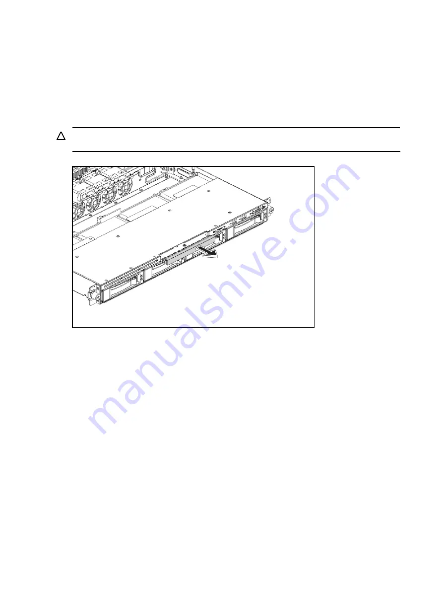
5.


Pull the bezel blank out of the carrier. 


CAUTION:

 Do not discard the bezel blank. If the optical drive is removed in the future, you must 

reinstall the bezel blank to maintain proper system function. 

Figure 9


Removing the Bezel Blank


To install the optical drive:  

1.


Slide the optical drive assembly into the chassis. 

2.


Remove the top cover, fasten the screws and connect the IDE data and power cables to their 
corresponding connectors on the optical drive. 

Содержание ProLiant DL160se - G6 Server

Страница 1: ...HP ProLiant DL160se G6 Server Maintenance and Service Guide Part number 516739 001 First edition April 2009 ...

Страница 2: ...set forth in the express warranty statements accompanying such products and services Nothing herein should be construed as constituting an additional warranty HP shall not be liable for technical or editorial errors or omissions contained herein Intel Xeon and Intel Core are trademarks or registered trademarks of Intel Corporation or its subsidiaries in the United States and other countries ...

Страница 3: ... installation procedure 30 Post installation instructions 30 Server warnings and cautions 31 Symbols on equipment 31 Powering down the server 32 System cover 33 Top cover 33 Drives 34 Cable management 34 Cable connections 35 Drive bay configuration 37 Optical Media Device Bay 39 Hard drives 42 SAS SATA HDD backplane 50 System board configuration 56 Processor 56 Memory 62 PCI expansion card 66 Dedi...

Страница 4: ...IOS software 101 BIOS Setup Utility 101 Accessing the BIOS Setup Utility 101 Navigating through the Setup Utility 102 Setup Utility menu bar 103 BIOS update 109 Clear CMOS 109 Power On Self Test POST 109 POST error indicators 110 POST errors Message Definition 110 POST related troubleshooting 110 SETSYS utility 111 Physical and operating specifications 112 System unit 112 Index 117 ...

Страница 5: ... be shipped for next business day delivery Same day or four hour delivery may be offered at an additional charge where geography permits If assistance is required you can call the HP Technical Support Center and a technician will help you over the telephone HP specifies in the materials shipped with a replacement CSR part whether a defective part must be returned to HP In cases where it is require...

Страница 6: ...èces CSR sont livrées le jour ouvré suivant dans la limite des stocks disponibles et selon votre situation géographique Si votre situation géographique le permet et que vous demandez une livraison le jour même ou dans les 4 heures celle ci vous sera facturée Pour bénéficier d une assistance téléphonique appelez le Centre d assistance technique HP Dans les documents envoyés avec la pièce de rechang...

Страница 7: ... con consegna entro il giorno lavorativo seguente La consegna nel giorno stesso o entro quattro ore è offerta con un supplemento di costo solo in alcune zone In caso di necessità si può richiedere l assistenza telefonica di un addetto del centro di supporto tecnico HP Nel materiale fornito con una parte di ricambio CSR HP specifica se il cliente deve restituire dei componenti Qualora sia richiesta...

Страница 8: ...innerhalb von vier Stunden gegen einen Aufpreis verfügbar Wenn Sie Hilfe benötigen können Sie das HP technische Support Center anrufen und sich von einem Mitarbeiter per Telefon helfen lassen Den Materialien die mit einem CSR Ersatzteil geliefert werden können Sie entnehmen ob das defekte Teil an HP zurückgeschickt werden muss Wenn es erforderlich ist das defekte Teil an HP zurückzuschicken müssen...

Страница 9: ...stino al siguiente día laborable Si la situación geográfica lo permite se puede solicitar la entrega en el mismo día o en cuatro horas con un coste adicional Si precisa asistencia técnica puede llamar al Centro de asistencia técnica de HP y recibirá ayuda telefónica por parte de un técnico Con el envío de materiales para la sustitución de componentes CSR HP especificará si los componentes defectuo...

Страница 10: ... verzonden voor levering op de eerstvolgende werkdag Levering op dezelfde dag of binnen vier uur kan tegen meerkosten worden aangeboden indien dit mogelijk is gezien de locatie Indien assistentie gewenst is belt u een HP Service Partner om via de telefoon technische ondersteuning te ontvangen HP vermeldt in de documentatie bij het vervangende CSR onderdeel of het defecte onderdeel aan HP moet word...

Страница 11: ...rimeiro dia útil após o pedido Onde as condições geográficas permitirem a entrega no mesmo dia ou em quatro horas pode ser feita mediante uma taxa adicional Se precisar de auxílio entre em contato com o Centro de suporte técnico da HP para que um técnico o ajude por telefone A HP especifica nos materiais fornecidos com a peça CSR de reposição se a peça com defeito deve ser devolvida à HP Nos casos...

Страница 12: ...Customer self repair 12 ...

Страница 13: ...Customer self repair 13 ...

Страница 14: ...Customer self repair 14 ...

Страница 15: ...Customer self repair 15 ...

Страница 16: ... Description Spare Part Number Customer Self Repair 1 Air baffle 519710 001 Mandatory1 2 Power supply cage 532473 001 Mandatory1 3 Rail kit 573091 001 Mandatory1 4 Hard drive cage 532114 001 Mandatory1 Hardware and Plastic Kit 5 BRKT FIXED PSU G6 SCR 6 32 X 157 T10 SCR TT 6 32x 160 SLT T15 BRKT Rear I O 1U G6 BLANK HDD SLIMLINE 536390 001 Mandatory1 6 Top cover 507262 001 Mandatory1 ...

Страница 17: ...Mandatory1 2 Rail kit 573091 001 Mandatory1 3 Hard drive cage 532473 001 Mandatory1 Hardware and Plastic Kit 4 BRKT FIXED PSU G6 SCR 6 32 X 157 T10 SCR TT 6 32x 160 SLT T15 BRKT Rear I O 1U G6 BLANK HDD SLIMLINE 536390 001 Mandatory1 5 Top cover 507262 001 Mandatory1 1 Mandatory Parts for which customer self repair is mandatory If you request HP to replace these parts you will be charged for the t...

Страница 18: ...zione ad HP deve sostenere le spese di spedizione e di manodopera per il servizio 2 Optional Opzionali Parti la cui riparazione da parte del cliente è facoltativa Si tratta comunque di componenti progettati per questo scopo Se tuttavia il cliente ne richiede la sostituzione ad HP potrebbe dover sostenere spese addizionali a seconda del tipo di garanzia previsto per il prodotto 3 No Non CSR Alcuni ...

Страница 19: ...reparatie door de klant Als u echter HP verzoekt deze onderdelen voor u te vervangen kunnen daarvoor extra kosten in rekening worden gebracht afhankelijk van het type garantieservice voor het product 3 No Nee Sommige HP onderdelen zijn niet ontwikkeld voor reparatie door de klant In verband met de garantievoorwaarden moet het onderdeel door een geautoriseerde Service Partner worden vervangen Deze ...

Страница 20: ...Illustrated parts catalog 20 ...

Страница 21: ...1 3 Non hot plug power supply 500 W 506247 001 Optional2 4 System board 519709 001 TBD 5 Memory modules Registered DIMMs RDIMMs DIMM 2GB 2Rx8 PC3 10600R 9 501533 001 Mandatory DIMM 4GB 2Rx4 PC3 10600R 9 501534 001 Mandatory DIMM 4GB 4Rx8 PC3 8500R 7 LP 501535 001 Mandatory DIMM 8GB 2Rx4 PC3 8500R 7 519201 001 Mandatory Unregistered DIMMs UDIMMs DIMM 1GB 1Rx8 PC3 10600E 9 501539 001 Mandatory DIMM ...

Страница 22: ...ers 72 GB 15 000 rpm 376594 001 Mandatory 146 GB 15 000 rpm 376595 001 Mandatory 300 GB 15 000 rpm 432146 001 Mandatory 400 GB 10 000 rpm 456896 001 Mandatory 450 GB 15 000 rpm 454274 001 Mandatory 750 GB 7 200 rpm 461288 001 Mandatory 1 TB 7 200 rpm 461289 001 Mandatory 3 5 hot plug SATA hard drives with carriers 160 GB 7 200 rpm 1 5Gbps 353043 001 Mandatory 160 GB 7 200 rpm 3 0Gbps 483095 001 Ma...

Страница 23: ...n hot plug power supply 500 W 506247 001 Mandatory1 4 System board 507255 001 Optional2 5 Memory modules Registered DIMMs RDIMMs DIMM 2GB 2Rx8 PC3 10600R 9 501533 001 Mandatory DIMM 4GB 2Rx4 PC3 10600R 9 501534 001 Mandatory DIMM 4GB 4Rx8 PC3 8500R 7 LP 501535 001 Mandatory DIMM 8GB 2Rx4 PC3 8500R 7 519201 001 Mandatory Unregistered DIMMs UDIMMs DIMM 1GB 1Rx8 PC3 10600E 9 501539 001 Mandatory DIMM...

Страница 24: ...001 Mandatory 146 GB 15 000 rpm 376595 001 Mandatory 300 GB 15 000 rpm 432146 001 Mandatory 400 GB 10 000 rpm 456896 001 Mandatory 450 GB 15 000 rpm 454274 001 Mandatory 750 GB 7 200 rpm 461288 001 Mandatory 1 TB 7 200 rpm 461289 001 Mandatory 3 5 hot plug SATA hard drives with carriers 160 GB 7 200 rpm 1 5Gbps 353043 001 Mandatory 160 GB 7 200 rpm 3 0Gbps 483095 001 Mandatory 250 GB 7 200 rpm 1 5...

Страница 25: ...PCIex16 riser card 511809 001 Mandatory 3 Non hot plug power supply 500 W 506247 001 Mandatory 4 System board 507255 001 Optional 5 Memory modules Registered DIMMs RDIMMs DIMM 2GB 2Rx8 PC3 10600R 9 501533 001 Mandatory DIMM 4GB 2Rx4 PC3 10600R 9 501534 001 Mandatory DIMM 4GB 4Rx8 PC3 8500R 7 LP 501535 001 Mandatory DIMM 8GB 2Rx4 PC3 8500R 7 519201 001 Mandatory Unregistered DIMMs UDIMMs DIMM 1GB 1...

Страница 26: ...f you request HP to replace these parts you will be charged for the travel and labor costs of this service 2 Optional Parts for which customer self repair is optional These parts are also designed for customer self repair If however you require that HP replace them for you there may or may not be additional charges depending on the type of warranty service designated for your product 3 No Some HP ...

Страница 27: ...nach den für Ihr Produkt vorgesehenen Garantiebedingungen zusätzliche Kosten anfallen 3 No Kein Einige Teile sind nicht für Customer Self Repair ausgelegt Um den Garantieanspruch des Kunden zu erfüllen muss das Teil von einem HP Servicepartner ersetzt werden Im illustrierten Teilekatalog sind diese Teile mit No bzw Nein gekennzeichnet 1 Mandatory Obligatorio componentes para los que la reparación ...

Страница 28: ...tão identificadas com a marca No Não no catálogo de peças ilustrado HP contact information For the name of the nearest HP authorized reseller In the United States call 1 800 345 1518 In Canada call 1 800 263 5868 In other locations refer to the HP website at http www hp com For HP technical support In North America Call 1 800 HP INVENT 1 800 474 6836 This service is available 24 hours a day 7 days...

Страница 29: ...tools You will need the following tools T 10 T 15 wrench The following references and software tools will assist with the hardware configuration HP ProLiant DL160se G6 Server Easy Set up CD IPMI Event Log Diagnostics Software Hardware configuration information Electrostatic discharge information An electrostatic discharge ESD can damage static sensitive devices or micro circuitry Proper packaging ...

Страница 30: ... 4 If server is installed in a rack remove server and place it on a flat surface 5 Remove the top cover according to the instructions described in the System cover section in this chapter 6 Follow the ESD precautions listed previously in this chapter when handling a server component IMPORTANT To streamline the configuration process read through the entire installation and removal procedures first ...

Страница 31: ...stem cover open or removed Operating the server in this manner results in improper airflow and improper cooling that can lead to thermal damage HP Trusted Platform Module The TPM is not a customer removable part CAUTION Any attempt to remove an installed TPM from the system board breaks or disfigures the TPM security rivet Upon locating a broken or disfigured rivet on an installed TPM administrato...

Страница 32: ...ines for manual material handling These symbols on power supplies or systems indicate that the equipment is supplied by multiple sources of power WARNING To reduce the risk of injury from electric shock remove all power cords to completely disconnect power from the system Powering down the server The server does not completely power down when the power button on the front panel is pressed The butt...

Страница 33: ... cover with a T 10 wrench 2 Press the latch on the top cover 3 Slide the cover toward the rear of the server and then lift the top cover to remove it from the chassis Lift the top cover away from the chassis Figure 1 Removing the Top Cover To reinstall the top cover 1 Align the top cover to the chassis and then slide it towards the front panel to position it into place 2 Once the cover is attached...

Страница 34: ...ent cutting or crimping When folding a flat ribbon cable never fold to a sharp crease Sharp creases may damage the wires Some flat ribbon cables come pre folded Never change the folds on these cables Do not sharply bend any cable A sharp bend can break the internal wires Never bend a SATA data cable tighter than a 30 mm 1 18 in radius Never crease a SATA data cable Do not rely on components like t...

Страница 35: ...hing power supply System board power backplane connector RPS Switching power supply Graph card power connector P4 Switching power supply 4 HDD hot plug Backplane power connector P5 Switching power supply 4 Non hot plug HDD P6 P7 P8 P9 Switching power supply 2 HDD hot plug Backplane power connector P10 P11 NOTE P6 P7 P8 P9 P10 and P11are extended connectors from P5 P4 are the extended 6 pin connect...

Страница 36: ... the System Board Cable To System Board Designator 20 pin front panel connector Front panel J42 USB 0 1 connector Front panel USB 2 0 J53 USB 4 connector Internal USB 2 0 J69 24 pin power connector Power supply J51 8 pin power connector Power supply J64 4 pin power connector Power supply J60 3 pin backplane I2 C connector Backplane J65 12 pin power supply EFF connector Power supply J79 16 pin powe...

Страница 37: ...connector Optical disc drive J57 Table 11 Drive Cable Connections 4 3 5 Non hot plug HDD Cable To System Board Designator SATA 1 connector HDD 1 J41 SATA 2 connector HDD 2 J49 SATA 3 connector HDD 3 J52 SATA 4 connector HDD 4 J55 SATA 5 connector Optical disc drive J57 Drive bay configuration The server supports a maximum of 2 to 5 drive bays 2 drive bays for 3 5 in hard disk drives or 2 drive bay...

Страница 38: ...mm 0 37 in DVD ROM optical drive optional 2 3 5 in hard disk drive bays 2 The HDD bays support both SATA and SAS drives Figure 5 System Drive Bays 4 3 5 HDD Hot plug Model Item Description 1 9 5mm 0 37 in DVD ROM optical drive optional 2 3 5 in hard disk drive bays 4 The HDD bays support both SATA and SAS drives ...

Страница 39: ...k drive bays 4 The HDD bays can support SATA drives Optical Media Device Bay The optical media device bays of the servers with 2 HDDs and 4 HDDs both support a 9 5 mm 0 37 in DVD ROM The following procedure is an example using the server with 4 HDDs model To remove the optical drive carrier 1 Remove the top cover and then unplug the SATA and power cables 2 Loosen the screws ...

Страница 40: ...s 3 Push the optical drive toward the front of the unit 4 Pull the optical drive out of the chassis Figure 8 Removing the Optical Drive IMPORTANT If you removed an optical drive without plans of installing a new one you must reinstall the blank to maintain proper system airflow ...

Страница 41: ...urface 4 Remove the top cover 5 Pull the bezel blank out of the carrier CAUTION Do not discard the bezel blank If the optical drive is removed in the future you must reinstall the bezel blank to maintain proper system function Figure 9 Removing the Bezel Blank To install the optical drive 1 Slide the optical drive assembly into the chassis 2 Remove the top cover fasten the screws and connect the I...

Страница 42: ...mmodate up to two or four hard drives You can install either SAS hard drives or SATA hard drives in the server For servers with 2 HDDs the hard drives installed in the server are labeled from Device 1 to Device 2 from left to right when viewed from the front of the server Figure 11 Hard Drive Configuration 2 3 5 HDD Hot plug Model ...

Страница 43: ...4 HDDs the hard drives installed in the server are labeled from Device 1 to Device 4 from left to right when viewed from the front of the server Figure 12 Hard Drive Configuration 4 3 5 HDD Hot plug Model Item Description 1 1st SAS SATA hard drive 2 2nd SAS SATA hard drive 3 3rd SAS SATA hard drive 4 4th SAS SATA hard drive ...

Страница 44: ...the servers with 2 3 5 HDDs and 4 3 5 HDDs share the same replacement procedures Here we take the server with 4 3 5 HDDs as an example for your reference To remove the hot plug hard drive 1 Press the hard disk carrier button to release the ejector lever 2 Use the HDD carrier latch to pull the drive out of the cage Make sure to support the drive when pulling it out of the cage 3 Pull the hard drive...

Страница 45: ...ive blank out of the chassis Figure 15 Removing the Hot plug Hard Drive Blank IMPORTANT Do not discard the hard drive blank If the drive is removed in the future you must reinstall the hard drive blank to maintain proper system airflow 2 Install a hard drive a Push the hard drive assembly into the drive bay until it stops b Press the HDD carrier latch inward until it clicks ...

Страница 46: ... Drive Assembly To remove the non hot plug hard drive 1 Disconnect the SATA and power cable 2 Loosen the screw with the T 10 T 15 wrench provided Figure 17 Loosening the Screw 3 Push the hard drive toward the front of the unit 4 Pull the hard drive assembly out of the drive bay ...

Страница 47: ...emoving the Non hot plug Hard Drive Assembly To remove a non hot plug hard drive disk from the carrier 1 Loosen the four screws on the carrier two on each side 2 Lift the hard drive from the carrier Figure 19 Removing the Non hot plug Hard Drive Disk ...

Страница 48: ...D to the carrier using the screws two on each side Figure 20 Installing the Non hot plug Hard Drive Disk into the Carrier To install a non hot plug hard drive into the server 1 Remove the hard drive blank from the front of the system if installed 2 Push the hard drive assembly into the drive bay until it stops Figure 21 Installing the Non hot plug Hard Drive Assembly ...

Страница 49: ...t procedures 49 3 Fasten the screw with the T 10 T 15 wrench provided to secure the hard drive to the chassis 4 Connect the cabling from the HDD backplane to the drive using the cables provided Figure 22 Fastening the Screw ...

Страница 50: ...wing figures show the front and back side of the backplane Figure 23 Backplane Connectors of Server with 2 HDDs component side Item Description 1 Screw holes 2 LED indicators 3 Headers for hard drive Figure 24 SAS Backplane Connectors of Server with 4 HDDs component side ...

Страница 51: ...ew holes 2 LED indicators 3 Headers for hard drive Figure 25 SATA Backplane Connectors of Server with 4 HDDs component side Item Description 1 Screw holes 2 LED indicators 3 Headers for hard drive Figure 26 Backplane Connectors of Server with 2 HDDs solder side ...

Страница 52: ... Description 1 Power connector 2 PROG connector 3 I2 C connector 4 Mini SAS connector Figure 27 SAS Backplane Connectors of Server with 4 HDDs solder side Item Description 1 Power connector 2 Mini SAS connector 3 PROG connector 4 I2 C connector ...

Страница 53: ...power switch is in the off position To remove the backplane The backplanes for the servers with 2 HDDs and 4 HDDs share the same replacement procedures Here we take the SAS backplane for the server with 4 HDDs as an example for your reference 1 Remove all drives out of the drive bays Refer to the Optical Media Device Bay and Hard drives sections in this chapter for detailed procedures 2 Remove the...

Страница 54: ...at secure the backplane to the hard drive cage c Pull the backplane up and out to release it from the hard drive cage Figure 30 Removing the Backplane To reinstall the backplane 1 Orient the backplane so that the notches on the backplane align with the hook on the drive cage and then press the backplane down until it clicks into place 2 Secure the backplane with three screws ...

Страница 55: ...Removal and replacement procedures 55 Figure 31 Reinstalling the Backplane 3 Install all cables ...

Страница 56: ...fails the system will be automatically booted from processor 1 and provide a processor failure message The processor socket supports 2P Intel Xeon processor with integrated memory controller CAUTION It is recommended to use processors of the same speeds or cache sizes to prevent possible server malfunction Figure 32 Processor Locations Item Description 1 Processor 1 2 Processor 2 WARNING To reduce...

Страница 57: ...the system board CAUTION Place the heat sink down in an upright position with the thermal patch facing upward Do not let the thermal patch touch the work surface Figure 34 Removing the Heat Sink Assembly IMPORTANT If the heat sink has been removed for any reason on a previously installed processor it is critical that you apply more grease compound to the integrated heat spreader on the processor t...

Страница 58: ...r 1 Unlock the load lever and lift it up 2 Open the retention plate 3 Grasp the processor by its edges and lift it out of its socket Figure 35 Removing the Processor CAUTION The pins of the socket are very fragile Do not bend or damage them CAUTION Place the processor on a static dissipating work surface or in an anti static bag CAUTION To allow heat sink to draw as much heat as possible from the ...

Страница 59: ...tsu X 23 7783D thermal grease compound for your ProLiant server Apply the grease to the top of the processor in either a 5 Dot or S shaped pattern Ensure even distribution Figure 36 The bottom of the heat sink CAUTION Never touch the bottom of the processor any contaminant could prevent the mounting pads from making contact with the socket CAUTION Applying too much grease creates a gap between the...

Страница 60: ...essor by its edges and align it over the empty processor socket Make sure that you properly align the processor with the orientation notch on the socket CAUTION To prevent overheating or a possible system crash use only a heat sink model specified for the HP ProLiant DL160se G6 server To install the heat sink 1 Properly align the heat sink spring loaded screws to the system board mounting holes 2 ...

Страница 61: ...board CAUTION For proper cooling do not operate the server without the top cover air baffle expansion slot covers or blanks installed For additional information see the user guide If hot plug components are supported minimize the amount of time the top cover is removed To install the air baffle 1 Connect all necessary cables 2 Gently place the air baffle on the system board Figure 39 Installing th...

Страница 62: ...e of the same type and speed Use 800 1066 1333 MHz DDR3 RDIMM UDIMM Installation guide for 1P configuration Follow the sequence of 2A 4B 6C 1D 3E and 5F for the corresponding processor when installing the memory Installation guide for 2P configuration Follow the sequence of 2A 4B 6C 1D 3E and 5F for the corresponding processor when installing the memory Install at least one memory DIMM for each pr...

Страница 63: ...edure see the Processor section in this chapter To remove the memory module 1 Completely open the holding clips securing the memory module 2 Gently pull the memory module upward to remove it from the slot Figure 42 Removing the Memory Module CAUTION Place the memory module on a static dissipating work surface or inside of an anti static bag ...

Страница 64: ...slot and then fully press the memory module into the slot until the holding clips snap back in place Figure 43 Installing the Memory Module CAUTION The DIMM slots are structured to ensure proper installation If you insert a DIMM but it does not fit easily into the slot you may have inserted it incorrectly Reverse the orientation of the DIMM and insert it again ...

Страница 65: ...ubsystem may be populated with either RDIMMs or UDIMMs but mixing the two types is not supported To determine DIMM characteristics use the label attached to the DIMM and the following illustration and table Item Description Definition 1 Size 2 Rank 1R Single rank 2R Dual rank 4R Quad rank 3 Data width x4 4 bit x8 8 bit 4 Memory speed 10600 1333 MHz 8500 1067 MHz 5 DIMM type R RDIMM registered E UD...

Страница 66: ...expansion slots on the system board Figure 44 System Board PCI Expansion Slots Item Component Designator Component Function 1 J31 PCIe X4 FH FL slot 1b Support a PCIe or PCI X riser card 2 J17 PCIe X16 FH FL slot 1a Support a PCIe or PCI X riser card 3 J18 PCIe X16 LP slot 2 Support a PCIe or PCI X riser card ...

Страница 67: ... Card using Slot 1a 1b on the system board or to replace the single Slot PCI Express riser card in Slot 1a and slot 2 with a PCI X model using the PCI X riser card option kit This will allow support for PCI X devices Figure 45 PCIe x16 Full Height Full Length Riser Card Connector Location the riser card for slot 1a Single slot PCIe riser card x16 link with x16 slot Figure 46 PCIe x16 Low Profile R...

Страница 68: ...E Disconnect all cables connecting an existing expansion board to the system board 1 Loosen the four screws that secure the PCI cage to the system board tray 2 Lift the PCI cage away from the system board assembly Figure 48 Removing the PCI Cage Installing PCIe PCI X riser cards The system supports up to two riser cards at a time Use only HP supported expansion boards that meet the following speci...

Страница 69: ...s installed Form Factor Low Profile Full Height Full Length To remove the PCIe riser card 1 Loosen the two screws securing the riser card to the PCI cage 2 Remove the riser card from the PCI cage Figure 49 Removing the PCIe x16 Full Height Full Length Riser Card Figure 50 Removing the PCIe x16 Low Profile Riser Card ...

Страница 70: ...ure 51 Removing the PCIX Full Height Full Length Riser Card To install the PCIe riser card 1 Align the screw holes on the riser card to the screw holes on the PCI cage 2 Install and tighten the screws that secure the riser card to the PCI cage ...

Страница 71: ...Removal and replacement procedures 71 Figure 52 Installing the PCIe x16 Full Height Full Length Riser Card Figure 53 Installing the PCIe x16 Low Profile Riser Card ...

Страница 72: ...Figure 54 Installing the PCIe PCIX Full Height Full Length Riser Card To install the PCI expansion board 1 Remove the screw near the slot cover on the PCI cage Figure 55 Removing the Screw on the PCI Cage on the Full height Full length Side ...

Страница 73: ...Screw on the PCI Cage on the Low profile Side 2 Remove the slot cover from the PCI cage 3 Slide the expansion board into the slot aligning the board with its matching connector Firmly press the board to seat it properly on the slot 4 Fasten the screw to secure it ...

Страница 74: ... reinstalled to maintain proper cooling To reinstall the PCI cage 1 Install the PCI expansion board into the PCI cage a Align the PCI expansion board with the open expansion slot b Press the PCI expansion board into the expansion slot on the riser card 2 Align the PCI cage to the system board expansion slot and then press it down to ensure full connection to the system board 3 Tighten the four scr...

Страница 75: ... and replacement procedures 75 Figure 59 Reinstalling the PCI Cage with PCI Expansion Board 1 Figure 60 Reinstalling the PCI Cage with PCI Expansion Board 2 4 Connect the necessary cable s to the system board ...

Страница 76: ...e 61 Dedicated management port Location To remove the dedicated management port 1 Remove the PCI cage assembly out of the chassis Refer to the PCI expansion card section in this chapter for detailed procedures 2 Loosen the screw 3 Pull the dedicated management port upwards and then remove the dedicated management port from the dedicated management port connector Figure 62 Removing the Dedicated ma...

Страница 77: ...nd replacement procedures 77 Figure 63 Removing the Spacer To reinstall the dedicated management port 1 Remove the mgmt port cover Figure 64 Removing the Mgmt Port Cover 2 Insert the spacer into the system board ...

Страница 78: ...nector 4 Tighten the screw clockwise to secure the dedicated management port to the system board Figure 66 Reinstalling the Dedicated management port System battery The server uses nonvolatile memory that requires a system battery to retain system information when power is removed This 3 V lithium coin cell battery is located on the system board ...

Страница 79: ...S settings whenever you replace the system battery NOTE If the server no longer automatically displays the correct date and time you may need to replace the system battery Under normal usage system battery life is five to ten years To replace the system battery 1 Power down the server 2 Disconnect the power cord s 3 Unlock the server if necessary and remove the top cover as described in the sectio...

Страница 80: ...BWC Optional This server can support a BBWC The BBWC is optional for the shipment Figure 69 BBWC Location To remove the BBWC assembly 1 Push the tab that secures the BBWC assembly to the system board tray 2 Slide the BBWC assembly and then lift it out of the system board assembly ...

Страница 81: ... Press the BBWC assembly into the tray and then push it along the direction of the arrow to lock the locking tabs Figure 71 Reinstalling the BBWC Assembly System board removal and replacement procedure To remove the system board 1 Remove the top cover 2 Remove the air baffle and all cables from the system board 3 Loosen the nine screws that secure the system board to the chassis ...

Страница 82: ...emoving the System Board To reinstall the system board 1 Align the system board I O connectors to their openings and slide the system board into place The nine screw holes on the chassis should align with the system board 2 Fasten the nine screws on the system board to secure the system board to the chassis Figure 73 Reinstalling the System Board ...

Страница 83: ...g 500 W non hot plug PSU or optional 750 W or optional 460 W hot plug PSU with PFC power factor correction function Figure 74 Hot plug Power Supply Unit Optional To remove the hot plug power supply 1 Press the port wine colored tab 2 Slide the hot plug power supply out of the power supply bay Figure 75 Removing the Hot plug Power Supply ...

Страница 84: ...einstalling the Hot plug Power Supply Figure 77 Non hot plug Power Supply Unit WARNING Take note of the following reminders to reduce the risk of personal injury from electric shock hazards and or damage to the equipment Installation of power supply units should be referred to individuals who are qualified to service server systems and are trained to deal with equipment capability of generating ha...

Страница 85: ...Two Screws beneath the Chassis 2 Loosen the screws that secure the power supply to the chassis 3 Pull and lift the power supply out of the chassis Figure 79 Removing the Non hot plug Power Supply To reinstall the non hot plug power supply 1 Locate and push the power supply to the proper place in the chassis 2 Fasten the power supply to the chassis using the screws as shown in the figure below ...

Страница 86: ... located beneath the chassis to secure the power supply Figure 81 Fastening the Two Screws beneath the Chassis System fan The server has six system fans located on the center wall of the chassis one is optional The figure below identifies the system fans by their device number and shows their corresponding cable connections ...

Страница 87: ...system board A new system fan can be installed to allow the server to operate properly in case a default system fan becomes defective To remove the system fan 1 Power down the server 2 Disconnect the power cord s 3 Unlock the server if necessary and remove the top cover as described in the section System cover 4 Disconnect the system fan cable from its corresponding board connector 5 Release the f...

Страница 88: ... Fan To reinstall the system fan 1 Put the system fan cable through the system fan cage 2 Hold the system fan and press the system fan into the system fan bracket 3 Connect the system fan cable to its corresponding board connector Figure 84 Reinstalling the System Fan ...

Страница 89: ... hard drives of the HP ProLiant DL160se G6 server Connectors and components Front panel components Figure 85 Front Panel Components 2 3 5 HDD Hot plug Model Item Description 1 Thumbscrews for rack mounting 2 Drive online error LED 3 Drive activity LED 4 Optical disc drive optional 5 Serial number pull tab 6 Front panel USB 2 0 port 0 1 7 Front UID LED switch 8 System health LED 9 NIC 1 activity LE...

Страница 90: ...ug Model Item Description 1 Thumbscrews for rack mounting 2 Drive online error LED 3 Drive activity LED 4 Optical disc drive optional 5 Serial number pull tab 6 Front panel USB 2 0 port 0 1 7 Front UID LED switch 8 System health LED 9 NIC 1 activity LED 10 Power LED switch 11 Hard drive activity LED 12 NIC 2 activity LED 13 Hard disk drive HDD bays ...

Страница 91: ... Item Description 1 Thumbscrews for rack mounting 2 Optical disc drive optional 3 Serial number pull tab 4 Front panel USB 2 0 port 0 1 5 Front UID LED switch 6 System health LED 7 NIC 1 activity LED 8 Power LED switch 9 Hard drive activity LED 10 NIC 2 activity LED 11 Hard disk drive HDD bays ...

Страница 92: ...on 1 Power supply cable socket 2 Serial port 3 VGA port 4 GbE LAN port for NIC 2 5 Dedicated management port optional 6 Low profile PCI expansion card slot cover 7 Full height full length PCI expansion card slot cover 8 T 10 T 15 wrench 9 Screws for PCI cage 10 Rear UID LED switch 11 GbE LAN port for NIC 1 12 Rear panel USB 2 0 port 2 3 ...

Страница 93: ...pply cable socket 2 Serial port 3 VGA port 4 GbE LAN port for NIC 2 5 Dedicated management port optional 6 Low profile PCI expansion card slot cover 7 Full height full length PCI expansion card slot cover 8 T 10 T 15 wrench 9 Screws for PCI cage 10 Rear UID LED switch 11 GbE LAN port for NIC 1 12 Rear panel USB 2 0 port 2 3 ...

Страница 94: ...PU2 Processor 2 7 J48 DIMM slot 6C for processor 1 8 J60 4 pin power connector 9 J43 DIMM slot 1D for processor 1 10 J51 System power connector 11 CPU1 Processor 1 12 J63 Fan 1 connector 13 J71 Fan 2 connector 14 J64 8 pin power connector 15 J62 J70 Fan connectors 3 4 fan 4 connector is optional 16 J69 Internal USB 2 0 port 4 17 J65 Backplane I2 C connector 18 J68 J67 Fan connectors 5 6 19 J66 Har...

Страница 95: ...2 0 port 0 1 25 J42 Front panel header 26 J29 TPM Connector 27 J27 System maintenance jumper 28 SATA SATA connectors 29 J31 PCIe slot Jumpers The system board contains a system maintenance jumper J27 Table 12 describes the jumper settings Table 12 System Maintenance Jumper Settings J27 Jumper Status default off A Clear CMOS B Clear password C Recovery BIOS D Recovery BMC E RTC reset ...

Страница 96: ... the server Front panel LED indicators The front panel LED indicators allow constant monitoring of basic system functions while the server is operating Figure 91 Front Panel LED Indicators Table 13 Front Panel LED Indicator Status Item LED indicator Status Description 1 Front UID LED switch Steady blue Identification Flashing blue The system is being remotely managed Off No identification 2 System...

Страница 97: ...ctivity Off No hard drive activity 6 Power LED switch Steady green The system has AC power and is turned on Steady amber The system has AC power but in standby mode Off No AC power to the system Optical drive activity LED indicator The optical drive has an activity indicator that indicates when the drive is reading media Figure 92 Optical drive activity LED indicator Table 14 Optical Drive Activit...

Страница 98: ... Hard Drive LED Indicator Table 15 Hard Drive LED Indicator Status Item LED indicator Status Description 1 Drive online error LED indicator Steady blue The drive is located Steady orange The drive is in a failed state Off The drive is not in a failed state 2 Drive activity LED indicator Flashing green The drive is in an activity state Off The drive is not in an activity state ...

Страница 99: ... 1 NIC activity LED indicator Flashing green Linked and activity on the network Off No connection or linking at 10 Mbps speed 2 NIC link LED indicator Flashing green LAN is active Steady green LAN is link Off No connection 3 Dedicated management LAN port activity LED indicator optional Flashing amber LAN is active 4 Dedicated management LAN port link LED indicator optional Steady green Linking at ...

Страница 100: ...indicator for use during troubleshooting operations Figure 95 System Board LED Indicator Table 17 BMC activity LED Indicator Status Item Component Status Description 1 BMC activity LED indicator Steady green BMC is power on and in initialization process Flashing green BMC activity Off AC is Off ...

Страница 101: ... such as serial console redirection PXE boot and much more Initialize hardware at boot up using POST routines During power on or warm reset the BIOS perform POST routines to test system components allocate resource for various hardware devices and prepare the system to boot to various operating systems BIOS Setup Utility The HP server BIOS Setup Utility is used to configure five primary menu selec...

Страница 102: ... Table 18 Setup Utility Navigation Keys Key Function and Select different screens and Select items in each menu Enter Tab or Shift Tab Select a field value or display a submenu screen Display more options for items marked with Esc Exit the CMOS Setup menu Configure the system time or change field F1 To bring up the General Help window The General Help window describes other Setup navigation keys t...

Страница 103: ...eon R CPU X5570 2 93GHz Speed 2933MHz Count 1 System Memory Select Screen Size 2048MB Select Item Change Field System Time 09 41 43 Tab Select Field System Date Thu 03 05 2009 F1 General Help System Serial Number F10 Save and Exit NIC 1 MAC Address 00 23 7D A1 44 98 ESC Exit NIC 2 MAC Address 00 23 7D A1 44 99 Asset Tag POST F1 Prompt Delayed V02 61 C Copyright 1985 2006 American Megatrends Inc Us...

Страница 104: ...ect Item IPMI Configuration Enter Go to Sub Screen BIOS Serial Console Configuration F1 General Help Trusted Computing F10 Save and Exit ESC Exit V02 61 C Copyright 1985 2006 American Megatrends Inc WARNING Incorrect settings may cause the server to malfunction To correct the settings press the F9 key to restore the default settings CPU Configuration Configure CPU settings CPU Bridge Configuration...

Страница 105: ...uration Select Screen Select Item Enter Go to Sub Screen F1 General Help F10 Save and Exit ESC Exit V02 61 C Copyright 1985 2006 American Megatrends Inc Status of BMC Display the status of BMC BMC Firmware Revision Display the current revision of the BMC firmware BMC IPMI FW Date Display the date of the BMC IPMI firmware BMC SDR Version Display the current version of the BMC SDR Set LAN Configurat...

Страница 106: ...Help F10 Save and Exit ESC Exit V02 61 C Copyright 1985 2006 American Megatrends Inc Boot Settings Configuration Configure settings during system boot Standard Boot Order View and configure standard boot order settings Hard Disk Drives Display HDD information if detect HDD installed USB Device Boot Priority Configure priority settings for USB devices Users can configure the BIOS to avoid attemptin...

Страница 107: ...tion Disabled Select Screen Select Item Enter Change F1 General Help F10 Save and Exit ESC Exit V02 61 C Copyright 1985 2006 American Megatrends Inc Use this menu to configure the following items Admin Password Indicate if an admin password has been installed to the system User Password Indicate if a user password has been installed to the system Change Admin Password Modify or change your admin p...

Страница 108: ...een F1 General Help F10 Save and Exit ESC Exit V02 61 C Copyright 1985 2006 American Megatrends Inc Use this menu to save changes or discard changes When you save and exit the server reboots Save Changes and Exit Save the changes you have made and exit the BIOS Setup Utility Discard Changes and Exit Exit the BIOS Setup Utility without saving the changes you have made Discard Changes Discard cancel...

Страница 109: ...ues 9 Press F10 to close the Setup Utility NOTE Clearing CMOS restore all system configurations and password default settings Power On Self Test POST Before you can use a server all devices must be tested and initialized and the operating system must be bootstrapped to the memory This is referred to as Power On Self Test or POST POST is a series of diagnostic tests that checks firmware and hardwar...

Страница 110: ...e Corrupted 613 Controller Operational Firmware Corrupted 624 Power Supply Failure or Power Supply Unplugged 622 Either Fan Failure or Fan Missing 194 CPUID Processor family are different 192 L3 cache size mismatch 197 Processor speeds mismatched 005 CMOS Checksum Bad 041 Display memory test failed 040 Refresh timer test failed 048 Password check failed 003 CMOS Battery Low 701 Insufficient Runtim...

Страница 111: ... properly installed on top of the processor All memory modules are properly installed If you have installed a PCI accessory board verify that the board is firmly seated and any jumpers on the board are properly set Refer to the documentation provided with the accessory board All internal cabling and connections are in their proper order If you have changed the jumpers on the system board verify th...

Страница 112: ...storage controller Integrated ICH10R SATA 6 port DVD Floppy interface Optional DVD SATA Optional Floppy USB only USB key Embedded video controller ServerEngines Pilot 2 management controller I O subsystem One PCIe x16 links with x16 slot PCIe x4 links with x4 slot One PCIe x16 links with x16 slot Memory Twelve DDR3 800 1066 1333 MHz RDIMM UDIMM slots up to 96 GB Default media storage Two bays hot ...

Страница 113: ... Rear panel System board System Health LED NIC 1 2 activity LED Power Switch LED Hard drive activity LED indicator UID Switch LED UID LED LAN link status BMC Activity LED Power supply unit 500 W non hot plug power supply 460 W hot plug power supply 750 W hot plug power supply Thermal solution Six system fans one is optional ...

Страница 114: ...Table 22 Environmental Specifications Item Description Temperature Operating Non operating Storage Wet bulb temperature 10 C to 35 C 50 F to 95 F 30 C to 60 C 22 F to 140 F 30 C to 60 C 22 F to 140 F 38 7 C 101 7 F Relative humidity Operating Non operating Storage 10 to 90 non condensing 5 to 95 5 to 95 Altitude Operating Non operating 0 to 3049 m 0 to 10 000 ft 0 to 9146 m 0 to 30 000 ft Thermal ...

Страница 115: ...power Maximum peak power 460 W N A Temperature range Operating Shipping 5 C to 50 C 40 C to 85 C Relative humidity Operating Non operating 5 to 95 relative humidity non condensing 5 to 95 relative humidity non condensing Table 24 Power Supply Specifications 500 W Non hot plug Item Description Dimensions H x W x D 40 mm x 86 mm x 280 mm 1 57 in x 3 39 in x 11 02 in Weight approximate 1 36 kg Input ...

Страница 116: ...sions H x W x D 38 48 mm x 86 36 mm x 190 5 mm 1 52 in x 3 4 in x 7 5 in Weight approximate 1 36 kg Input requirements Rated input voltage Normal line voltage 90 VAC to 264 VAC 100 VAC to 120 VAC 200 VAC to 240 VAC Line frequency 47 63 Hz Rated input current 9 10 ARMS max 100V 5 10 ARMS max 200V BTU rating N A Power supply output power Rated steady state power Maximum peak power 750 W N A Temperat...

Страница 117: ...y 106 BIOS software 106 BIOS update 114 POST 114 Diagnostic tools and Setup Utilities clear CMOS 114 drive bay configuration 41 drives backplane 54 cable connections 39 cable management 38 drive bay configuration 41 hard drives 46 optical media drive 43 E electric shock symbol 34 warning 34 environmental specifications 119 exploded view Mechanical Components Spare Parts List 2 3 5 16 Mechanical Co...

Страница 118: ...s 31 I improper airflow caution 34 L LAN controller 117 LED indicator system board LED 105 LED indicators LAN 104 optical drive activity 102 M mechanical components 2 3 5 16 mechanical components 4 3 5 17 memory module installing 68 removing 67 memory modules spare part number 21 22 24 25 27 28 N non hot plug hard drive disk installing 52 non hot plug PSU reinstalling 90 removing 90 O onboard cont...

Страница 119: ...curity menu 112 specifications physical and operating 117 storage controller 117 symbols on equipment 34 system battery replacing 84 system board components 99 dimensions 119 LED 105 platform 119 reinstalling 86 spare part number 21 24 27 system components 2 3 5 21 system components 4 3 5 24 27 system cover top cover 37 system fan installing 93 removing 92 system fans spare part number 23 26 28 sy...

Отзывы: