HP OmniBook 4000 Скачать руководство пользователя страница 1

1

This guide is for experienced HP Response Center
personnel, CEs, and reseller technicians, such as
personnel who have already completed the HP Vectra
PC family training course, or equivalent, and have at
least six months of experience servicing the HP
Vectra PCs.

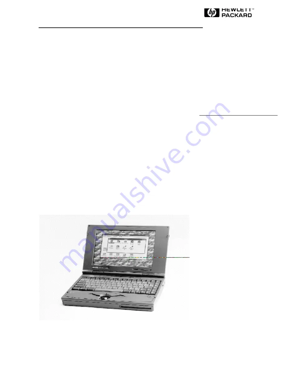
It is a self-paced guide designed to train you to install,
configure, and repair the OmniBook Notebook PC.
You can follow it without having any equipment
available.

HP OmniBook 5000C/CT

Familiarization Guide

Содержание OmniBook 4000

Страница 1: ...ted the HP Vectra PC family training course or equivalent and have at least six months of experience servicing the HP Vectra PCs It is a self paced guide designed to train you to install configure and repair the OmniBook Notebook PC You can follow it without having any equipment available HP OmniBook 5000C CT Familiarization Guide ...

Страница 2: ...rgy efficiency All Certifications may not be completed at product introduction Please check with your HP reseller for certification status This equipment is subject to FCC rules It will comply with the appropriate FCC rules before final delivery to the buyer ENERGY STAR is a service mark of the U S Environmental Protection Agency IBM and OS 2 are registered trademarks of International Business Mac...

Страница 3: ...e Memory Configurations 15 Mass storage 16 Flexible disk drive 17 Built in I O 17 Display Video 18 TFT Display Quality 18 User interface 19 Power 20 Battery Life rundown data approx 20 External battery charger 21 Automobile adapter 21 NiMH battery pack 21 LiIon battery pack 21 AC adapter 21 Accessory Slots 21 Audio Systems 21 Operating environment 22 Storage environment 22 Environmental Testing 22...

Страница 4: ...over Assembly and Icon Board PCB Assy PI ICON HP Authorized Service Providers Only 35 CPU Module and Heat Sink HP Authorized Support Providers Only 38 System Board PCB Assy PI 586 HP Authorized Support Providers Only 40 Configuration and Setup 42 Main Configuration Screen 42 Power Screen 43 Power Configuration 44 System Configuration 45 Input Output Configuration 46 COM Ports 46 Disk Configuration...

Страница 5: ...ure 7 Lower Case Screws 32 Figure 8 Palm Rest and Track Ball Assemblies 33 Figure 9 Keyboard and Power Board 34 Figure 10 Heat Spreader Assembly 36 Figure 11 Upper Cover and Icon Board 37 Figure 12 CPU Module and Heat Sink 39 Figure 13 System Board 41 Figure 14 Main Configuration Screen 42 Figure 16 System Configuration Screen 45 Figure 17 Input Output Screen 47 Figure 18 Disk Configuration Screen...

Страница 6: ...els include 256 KB external L2 cache No L2 cache No L2 cache Display 10 4 inch diagonal VGA C CT 640 x 480 x 65 536 colors DSTN or TFT SVGA CTS 800 x 600 x 256 colors TFT PCI local bus video 1 5 MB video RAM SVGA out supports VGA SVGA monitors up to 1024 x 768 x 256 colors 10 3 diagonal DSTN up to 256 colors or 10 4 inch diagonal TFT up to 65 536 colors VGA 640 x 480 Local bus video 1 MB display R...

Страница 7: ...p to 3 0 3 5 hours Battery pack recharges to high level in less than 2 hours using AC adapter 2 minute or less low battery warning AC adapter 100 to 240 Vac 50 to 60 Hz input 12 Vdc 2 5 A output Instant on maintains computer in ready to work state for months on a charge Turn it on again and you re instantly back where you were Removable Modules Floppy disk drive can be replaced with a second batte...

Страница 8: ...65 536 colors 115 200 baud bidirectional infrared Expansion bus connector SCSI 2 port NTSC PAL video out port Keyboard mouse port Headphone stereo out port Stereo in and microphone ports MIDI joystick port 9 pin 115 200 b s RS 232 port 25 pin EPP and ECP parallel port SVGA out up to 1024 x 768 x 256 115 200 baud bi directional infrared Expansion bus connector Keyboard mouse port Headphone stereo o...

Страница 9: ...ator with EPP parallel serial VGA out up to 1024 768 keyboard PS 2 or Microsoft mouse and SCSI ports external floppy connector and optional HP EtherTwist LAN card slot Pre installed Software Microsoft Windows 95 or Microsoft Windows for Workgroups 3 11 MS DOS 6 22 Plug and Play BIOS HP PIM dual loaded Microsoft Windows for Workgroups 3 11 MS DOS 6 22 Laplink Remote Access Easy connection to your d...

Страница 10: ...Battery TFT VGA Display One year warranty F1128A HP OmniBook 5000CT P 90 PCI BUS 1 2GB HD Drive 8MB RAM NiMH Battery VGA TFT Display One year warranty F1129A HP OmniBook 5000CT P 90 PCI BUS 1 2GB HDD 8MB RAM L2 cache SCSI LiIon Battery VGA TFT Display Three year warranty F1130A HP OmniBook 5000CTS P 90 PCI BUS 1 2GB HDD 16MB RAM L2 cache SCSI LiIon Battery SVGA TFT Display Three year warranty F113...

Страница 11: ...year warranty F1152A HP OmniBook 5000CT P 90 PCI BUS 1 2GB HDD 32MB RAM L2 cache SCSI LiIon Battery VGA TFT Display Three year warranty F1153A HP OmniBook 5000CTS P 90 PCI BUS 1 2GB HDD 8MB RAM L2 cache SCSI LiIon Battery SVGA TFT Display Three year warranty F1154A HP OmniBook 5000CTS P 90 PCI BUS 1 2GB HDD 32MB RAM L2 cache SCSI LiIon Battery SVGA TFT Display Three year warranty F1155A HP OmniBoo...

Страница 12: ...MB RAM NiMH Battery TFT Display One year warranty F1342A HP OmniBook 5000C P 120 PCI BUS 1 2GB HD Drive 16MB RAM NiMH Battery VGA DSTN Display Three year warranty F1343A HP OmniBook 5000CTS P 120 PCI BUS 1 2GB HD Drive 32MB RAM NiMH Battery SVGA TFT Display Three year warranty F1343A ...

Страница 13: ...ength ISA slots parallel serial SVGA out keyboard PS 2 mouse audio MIDI Joystick SCSI 2 ports supports PnP and hot docking Motorized docking to ensure solid dock Docking system only for the OmniBook 5000 F1189A OmniBook 5000 enhancements over the OmniBook 4000 Pentium P54LM CPU 90 MHz Opti Viper chip set Add L2 cache option 256KB Chips and Technologies Inc 65545 PCI bus VGA Controller with 1 5 MB ...

Страница 14: ...nd Deskjet 320 Microprocessor Intel Pentium 120MHz w L2 Cache 256K synchronous burst cache Intel Pentium 90 MHz w L2 Cache 256K synchronous burst cache The 90 MHz from Intel is a P54LM chip which has a core voltage of 2 9 volts Internal CPU bus speed 90MHz External bus speed 60MHz PCI bus speed 33MHz Intel Pentium 75 MHz currently does not have L2 cache Bus Architecture PCI Peripheral Component In...

Страница 15: ... 32 MB RAM p n F1136A RAM Manufacturer Multiple Vendors NEC Samsung etc Cycle time 70 ns Possible Memory Configurations Memory Slot 1 Memory Slot 2 Total RAM 8MB 8MB 8MB 8MB 16MB 8MB 16MB 24MB 8MB 32MB 40MB 16MB 16MB 16MB 8MB 24MB 16MB 16MB 32MB 16MB 32MB 48MB 32MB 32MB 64MB ...

Страница 16: ...d 12 ms 12 ms 12 ms 12 ms Track to track seek 3 ms 3 ms 4 ms 4 ms Full Track NA 25 ms 23 ms 23 ms Average latency 7 5 ms 7 1 ms 6 1 ms 6 1 ms Rotational speed 4000 rev m 4200 rev m 4900 rev m 4900 rev m Data transfer rate Media Transfer rate 18 9 31 6 Mbits sec 43 75 Mbits sec max 36 3 inner 57 0 Outer Mbits sec 36 3 inner 57 0 Outer Mbits sec Buffer to host 6 Mbytes sec 11 1Mbytes sec 11 1Mbytes ...

Страница 17: ...andard on all models The flexible disk drive can be easily removed by the user and replaced with an additional battery pack to double battery life This is part of the modularity features of the OmniBook 5000 Manufacturer F1079A Canon F1079B NEC subject to change Built in I O 9 pin 115 000 b s RS 232 port UART 16550 25 pin bi directional ECP and EPP parallel port SVGA out up to 1024 x 768 x 256 col...

Страница 18: ...mode Resolution options Resolution Maximum colors 640 x 480 64K 800 x 600 64K 1024 x 768 256 00 Auto detection of external monitor without rebooting Note Includes option to simultaneously display external video and notebook display TFT Display Quality TFT display manufacturing is a high precision but imperfect technology and manufacturers cannot currently produce large displays that are cosmetical...

Страница 19: ...sidered for replacement it should be clear to the customer that cosmetic variations on the replacement display may also exist and may require the customer to use a work around to obscure the cosmetic imperfection 4 Customers with cosmetic based complaints only that do not conform to the above conditions and tests will not normally be considered for display replacement It will be left to the judgme...

Страница 20: ...45 min 6 hrs 45 min If unit has 2 LiIon 4 hrs 4 hrs 8 hrs User can utilize any combo of LiIon and NiMh batteries in the OB5000 Low battery signals 2 minute low battery warning Unit will shut down if battery warning ignored to ensure data retention Instant on Maintains OmniBook in ready to work state for weeks on a full charge when turned on it returns instantly to previous state No waiting for res...

Страница 21: ...ated no weight estimate at this date Charges both the NiMh and LiIon batteries HP part number F1074A Automobile adapter HP part number F1064A same as OmniBook 600 NiMH battery pack HP part number F1073A LiIon battery pack HP part number F1137A AC adapter HP part number F1044B same as OmniBook 600 Accessory Slots User available PCMCIA Slots 2 Type II or 1 Type III Bus Intel QuickSwap ExCa The PCMCI...

Страница 22: ... as per IEC 801 2 EN 55024 2 Drop testing 1 drop flat onto all six faces from 75 meter Also tests for altitude magnetic radiated susceptibility interference shock vibration Note These are the tests that HP designs notebook computers to meet Due to normal variations in the components of individual machines some machines will perform better and some won t perform as well HP does not guarantee that e...

Страница 23: ... can be entered 3 The user reads the encoded master password to Support 4 Support runs a program that decodes the encoded password and reads the decoded password alphanumeric to the user 5 The user types in the decoded password 6 OmniBook decodes the encoded master password it generated and compares it to the decoded password typed in by the user 7 If the two passwords match the OmniBook is unlock...

Страница 24: ...owner of the unit The statement can be a FAX copy of the document The fact that the unit is in the hands of an HP representative on the behalf of the customer is not evidence of ownership In addition HP will not descramble a unit for any non owner even if it involves law enforcement agencies If you receive such a request you should notify management and HP Corporate Legal immediately These request...

Страница 25: ...00 family has two memory locations for expanding system RAM The memory locations are under the cover on the back of the computer Remove the cover by lifting at the finger indent The factory installed RAM module is located in the back pair of sockets To add an additional 8MB 16MB or 32MB of RAM use the front location To expand beyond 40MB or 48MB of memory you must discard the factory installed car...

Страница 26: ... are user replaceable A second Battery Module may be installed in the Floppy Disk Drive Bay This doubles the battery life of the OmniBook 5000 To remove either module turn the OmniBook over Squeeze the two levers together and slide the module forward Warning Be careful not to short the terminals on the battery This can generrate a lot of heat causing burns and fire as well as damage to the battery...

Страница 27: ... is not strong enough use the back edge of the module in front of the depression in the bottom case instead Reverse the procedure for installation To ensure proper pin placement hold the Hard Disk Drive by the sides being careful not to touch the pins Turn the OmniBook on its backplane where all the ports are and place the hard drive into the slot and allow gravity to drop the drive down the remai...

Страница 28: ...rom backcase Continue to flex until side pins clear holes in back case To reassemble simply reverse the procedure The expansion door is removed by opening it fully and flexing it in the middle until the pins in the backcase disengage from the slots in the side of the door To reassemble reverse the procedure The rubber feet are adhered to the bottom case with adhesive The memory door snaps on and o...

Страница 29: ...e feet and withdraw the two Phillips screws from under the feet in the bottom back corners of the unit see illustration below Turn the unit right side up and dislodge the Icon assembly by placing the thumbs on each edge of the assembly and pushing lightly see illustration below The front edge of the Icon Assembly will lift up slightly Display Chassis Screw 2 Figure 4 Display Screws ...

Страница 30: ... is being removed Otherwise slide the connector sleeve up to remove the Icon Assembly cable If only the Icon assembly is to be removed the display may be lowered back into position To remove the Display Assembly remove the two cables attaching the display module to the PC board Lastly remove the two screws attaching the grounding straps to the PC board The display can now be removed the rest of th...

Страница 31: ...of the Icon Assy tunnel When reinstalling the Display Module make sure that the two posts on either side of the display line up parallel with their slots in the top case If they are not parallel the post will get caught inside the top case before the display is seated completely If this happens remove the display and line the posts up properly Figure 6 Display Removal ...

Страница 32: ...each bay Remove these screws while the unit is upside down If the keyboard is to be removed withdraw the two Phillips screws under the Hard Disk Drive as shown in the illustration below Turn the unit right side up open the lid and lift up on the Palmrest Disconnect the cable attaching the Palmrest to the Track Ball Assembly To remove the Track Ball Assembly disconnect the Track Ball Assembly cable...

Страница 33: ...33 To replace reverse the above procedure Palm Rest Screw Figure 8 Palm Rest and Track Ball Assemblies ...

Страница 34: ... the Keyboard Assembly lift the front edge of the keyboard and rotate the keyboard up Next remove the connecting PC board by pulling up on the pull tabs attached to the back The cables can then be disconnected by sliding the sleeves out on the connecting PC board connectors Figure 9 Keyboard and Power Board ...

Страница 35: ... Spreader Assembly Removal Procedure 1 Remove Battery and Hard Disk Drive 2 Follow the Icon Assembly and Display Module Removal Procedures to remove these components 3 Follow the Keyboard Assembly and Power Board Removal Procedure to remove these components 4 Remove the Heat Spreader by unfastening the two Heat Spreader CPU Screws the Display Chassis Screw and the Palm Rest Screw see illustration ...

Страница 36: ...t free see illustration below The Microphone Assembly may dislodge from the Upper Cover during removal If it does not gently pull the Microphone Assy from the pocket in the Upper Cover If necessary the Microphone Assy may be removed from the Icon Board at this point Heat Spreader CPU Screws 2 Heat Pipe Bracket Display Chassis Screw Heat Spreader Assembly Palm Rest Screw Figure 10 Heat Spreader Ass...

Страница 37: ...ack while pulling upward until the pins dislodge from the connector Replacement Procedure 1 Reverse the Removal Procedure with the replacement component s Palm Rest Screw Icon Board PCB Assy PI ICON Microphone Assy Upper Cover Assy Track Ball Flex Cable FPC T B to M B Screw ISOT M2 6x6L Figure 11 Upper Cover and Icon Board ...

Страница 38: ...nts Note the Icon Board does not need to be removed to gain access to the CPU Module and Heat Sink However removing it does create additional space for maneuverability 5 Remove the two screws located towards the back of the CPU Module see below illustration 6 A portion of the Heat Sink is located underneath the CPU Module However removing the Heat Sink prior to the CPU Module facilitates the remov...

Страница 39: ...39 CPU Module Heat Sink Print Port Door Expansion Door I O Door PCMCIA Shield Screw ISOP M2 6x4L Figure 12 CPU Module and Heat Sink ...

Страница 40: ...ocedure to remove these components 4 Follow the Upper Cover and Icon Board PCB Assy PI ICON Removal Procedures to remove these components 5 Follow the CPU Module and Heat Sink Removal Procedures to remove these components 6 Disconnect the Track Ball Flex Cable FTB T B to M B see Figure 11 7 Remove the five Palm Rest Screws and three Standoffs see below illustration 8 Lift the PCMCIA Shield off of ...

Страница 41: ...off 11 75 mm Standoff 13 8 mm Contact Spring Docking Pin Palm Rest Screws 5 IR Lens Bezel Assy Editor s Note The PCMCIA Shield must be removed prior to the System Board Lower Cover Assy PCMCIA Button Assy Figure 13 System Board ...

Страница 42: ...guration utility Users can check system configuration and changes settings using f keys from this screen This is the most accurate place to check battery and system status Pressing f3 from this screen exits back to the current application The setup configuration utility is operating system independent ...

Страница 43: ...battery The auxiliary battery charge status does not show up if no auxiliary battery is installed Power conservation settings consists of the options shown which allow customer selection of Turn OFF instant off Auto Save to disk HDD power down and CPU power down Figure 15 Power Control Screen ...

Страница 44: ...led it will stay in Run Auto Save to disk Disable Time 6 hours to 7 days or never 1 day How long the system will be in off before the entire state of the computer the suspend state If disabled it will stay in the suspend state HDD power down Disable Time 1 30 minutes or never 3 minutes HDD will turn off system has ability to run HDD will spin up when access required CPU power down 512ms 8seconds 2...

Страница 45: ... clock is not changed until the user exits the setup program The user can also enable or disable the processor cache When the user decides to enable a password a pop up window requests the old password new password and confirmation of the new password Hard drives or mass storage are not affected by the password only the turn on condition Figure 15 System Configuration Screen ...

Страница 46: ...2 Addr 278 LPT3 Addr 3BC LPT1 Addr 378 LPT Type Bi directional PS 2 Standard AT Centronics Bi directional Keyboard Setup Key Delay 1 4 1sec Key Repeat Rate 2cps 30csp Key Delay 1 2 sec Key Repeat Rate 10CPS External Devices VGA Display Device Television type VGA Display Device external VGA if attached LCD off Television type NTSC on option ABA units Audio Ports Audio volume Beeper volume Audio vol...

Страница 47: ...47 Figure 16 Input Output Screen ...

Страница 48: ...Default Comments Floppy Disk Drive Disk A None 1 44MB 2 88MB 1 44MB Hard Disk Drive None Standard Custom Auto ID Auto ID Also reports disk drive data cylinders heads sectors tracks landing zone write precomp Figure 17 Disk Configuration Screen ...

Страница 49: ... These multiple beep codes indicate a failure in a simple test of a portion of base memory Flash BIOS checksum a portion of conventional memory a portion of extended memory If the unit fails to boot All accessories are removed including memory cards external floppy port expander modems PCMCIA cards LAN cards printers VGA out cables external pointing devices clean AC power is provided no chained ba...

Страница 50: ...s and count register test in progress or failure Failure will result in a system halt 1 2 3 DMA page register write read test in progress or failure Failure will result in a system halt 1 3 1 RAM refresh verification test in progress or failure Failure will result in a system halt 1 3 2 SMI RAM Bad Failure will result in a system halt None First 64K RAM test in progress No specific test is perform...

Страница 51: ... screen The system does not halt 4 2 2 Shutdown test in progress or failure If possible the BIOS will continue POST skipping the memory tests 4 2 3 Gate A20 failure An error message is displayed on the screen and the memory tests are suspended The system does not halt 4 2 4 Unexpected interrupt in protected mode The system does not half when an unexpected interrupt occurs 4 3 1 RAM test of memory ...

Страница 52: ...t to interpret a failure code immediately as a hardware failure until all accessories are removed including memory cards external floppy port expander modems PCMCIA cards LAN cards printers VGA out cables external pointing devices clean AC power is provided no chained battery chargers or auto adapters and press reset If the unit still fails to boot it requires service NOTE make sure the display is...

Страница 53: ... switch is set incorrectly The primary video adapter failed Gate A20 failure The keyboard controller is not accepting commands specifically the enable and disableA20 commands Fixed disk configuration error The specified configuration is not supported or doesn t match the actual hardware Fixed disk controller failure The controller card has failed Fixed disk failure The fixed disk may be defective ...

Страница 54: ... key is jammed Memory failure at hex value read hex value expecting hex value Circuitry associated with the memory chips has failed Unexpected interrupt in protected mode Hardware interrupt or NMI occurred while in protected mode Real time clock failure The RTC or battery failed Message Possible Cause nnnk Base Memory The amount of base memory that tested successfully nnnk Extended The amount of e...

Страница 55: ...Keyboard DAN F1125 60907 none Keyboard SWE FIN F1125 60908 none Keyboard EURO ENG F1125 60909 none Keyboard NOR F1125 60910 none Keyboard KOR F1125 60911 none Icon Assembly F1125 60912 none Y Keyboard Cable F1125 60913 none Trackball Assembly F1125 60921 none Palmrest Assembly F1125 60922 none Keyboard US F1125 60923 none Rubber Foot BACK F1081 60933 none Rubber Foot FRONT F1081 60934 none Disp Ch...

Страница 56: ...Heat Sink B F1125 60939 none PCMCIA Shield F1125 60940 none Heat Sink C F1125 60941 none LED Lens F1125 60942 none Lower Cover Assy F1125 60943 none BEZEL Assy F1125 60944 none Upper Cover Assy F1125 60945 none Rubber Pad K B F1125 60946 none Standoff 13 8mm F1125 60947 none Conduct Sponge 10X1X20mm F1125 60949 none PCB Assy PI 586 w SCSI Rev F F1125 60950 F1125 69002 Flash ROM BIOS Label F1125 60...

Отзывы: