48
Configuring an ADSL/G.SHDSL interface
Overview
The ADSL interface and the G.SHDSL interface support IPoA, IPoEoA, PPPoA, and PPPoEoA.
IPoA
IPoA enables IP packets to traverse an ATM network. In an IPoA implementation, ATM provides the data
link layer for the IP hosts on the same network to communicate with one another, and IP packets must be
adapted in order to traverse the ATM network.
IPoA makes full use of the advantages of ATM, including high speed point-to-point connections, which
help improve the bandwidth performance of an IP network, excellent network performance, and
complete, mature QoS services.
IPoEoA
IPoEoA adopts a three-layer architecture, with IP encapsulation at the uppermost layer, IPoE in the middle,
and IPoEoA at the bottom.
IPoEoA is suitable where Ethernet packets are to be forwarded through an ATM interface. For example,
it works when a network device forwards traffic from an Ethernet across an ATM PVC to a network access
server.
PPPoA
PPPoA enables ATM to carry PPP protocol packets. With PPPoA, PPP packets, in which IP packets or other
protocols' packets can be encapsulated, are encapsulated in ATM cells. In this case, ATM can be simply
viewed as the carrier of PPP packets. As the communication process of PPPoA is managed by PPP, PPPoA
inherits the flexibility and comprehensive applications of PPP.
PPPoEoA
PPPoEoA enables ATM to carry PPPoE protocol packets. With PPPoEoA, Ethernet packets are
encapsulated in ATM cells, through which you can use a PVC to simulate all the functions of Ethernet. To
allow ATM to carry Ethernet frames, the interface management module provides the VE interface. The VE
interface has Ethernet characteristics and can be dynamically created through configuration commands.
The following is the protocol stack adopted by the VE interface:
•
ATM PVC at the bottom layer
•
Ethernet at the link layer
•
Protocols the same as those for a common Ethernet interface at the network layer and upper layers
Configuration procedure
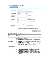
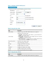
To configure an ADSL/G.SHDSL interface:
1.
Select
Interface Setup
>
WAN Interface Setup
from the navigation tree.
2.
Click the
icon for the ADSL/G.SHDSL interface.
3.
Configure the ADSL/G.SHDSL interface, as described in
.
Содержание MSR SERIES
Страница 17: ...xv Documents 835 Websites 835 Conventions 836 Index 838 ...
Страница 20: ...3 Figure 3 Initial page of the Web interface ...
Страница 42: ...25 Figure 13 Firefox Web browser setting ...
Страница 59: ...42 Figure 27 Checking the basic service configuration ...
Страница 73: ...56 Figure 35 Sample interface statistics ...
Страница 156: ...139 Figure 139 Rebooting the 3G modem ...
Страница 168: ...151 Figure 152 Configuring Web server 2 ...
Страница 174: ...157 Figure 158 Configure the URL filtering function ...
Страница 187: ...170 Upon detecting the Land or Smurf attack on Ethernet 0 2 Router outputs an alarm log and drops the attack packet ...
Страница 242: ...225 Figure 233 Enabling the DHCP client on interface Ethernet 0 1 ...
Страница 247: ...230 Figure 236 The page for configuring an advanced IPv4 ACL ...
Страница 255: ...238 Figure 241 Advanced limit setting ...
Страница 298: ...281 e Click Apply 2 Configure Router B in the same way Router A is configured ...
Страница 354: ...337 Figure 339 Configuring a login control rule so Host B cannot access Router through the Web ...
Страница 400: ...383 Figure 387 Verifying the configuration ...
Страница 405: ...388 ...
Страница 523: ...506 Figure 530 Ping configuration page ...
Страница 538: ...521 a Click Device A on the topology diagram b Click Ethernet 0 2 on the panel diagram c Click Port Guard ...
Страница 744: ...727 Verifying the configuration In the case that the IP network is unavailable calls can be made over PSTN ...
Страница 775: ...758 Figure 785 Configuring a jump node ...
Страница 791: ...774 Figure 801 Configuring a jump node ...


