586
NOTE:
•
The packet assembly interval is the duration to encapsulate information into a voice packet.
•
Bytes coded in a time unit = packet assembly interval × media stream bandwidth.
•
Packet length (IP) = IP RTP UDP voice information length = 20+12+8+data.
•
Packet length (IP+PPP) = PPP IP RTP UDP voice information length
= 6+20+12+8+data.
•
Network bandwidth = Bandwidth of the media stream × packet length/bytes coded in a time unit.
Because IPHC compression is affected significantly by network stability, it cannot achieve high efficiency
unless the line is of high quality, the network is very stable, and packet loss does not occur or seldom
occurs. When the network is unstable, IPHC efficiency drops drastically. With best IPHC performance,
the IP (RTP) header can be compressed to 2 bytes. If the PPP header is compressed at the same time, a
great deal of media stream bandwidth can be saved. The following table shows the best IPHC
compression efficiency of codec algorithms with a packet assembly interval of 30 milliseconds.
Table 225
Compression efficiency of IPHC+PPP header
Codec
Bytes
coded in
a time
unit
Before compression
After IPHC+PPP compression
Packet length
(IP+PPP) (bytes)
Network
bandwidth
(IP+PPP)
Packet length
(IP+PPP) (bytes)
Network
bandwidth
(IP+PPP)
G.729
30
76
20.3 kbps
34
9.1 kbps
G.723r63
24
70
18.4 kbps
28
7.4 kbps
G.723r53
20
66
17.5 kbps
24
6.4 kbps
G.726r16
60
106
28.3 kbps
64
17.1 kbps
G.726r24
90
136
17.5 kbps
94
25.1 kbps
G.726r32
120
166
44.3 kbps
124
33.1 kbps
G.726r40
150
196
52.3 kbps
154
41.1 kbps
Other parameters
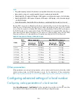
Other parameters are some optional parameters, such as number selection priority, dial prefix, called
number sending mode, and DTMF transmission mode. For the description of these parameters,
Configuring other parameters of a local number
Configuring other parameters for a call route
Configuring advanced settings of a local number
Configuring coding parameters of a local number
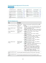
Select
Voice Management
>
Local Number
from the navigation tree, and then click the
icon of the
local number to be configured to access the advanced settings configuration page.
Содержание MSR SERIES
Страница 17: ...xv Documents 835 Websites 835 Conventions 836 Index 838 ...
Страница 20: ...3 Figure 3 Initial page of the Web interface ...
Страница 42: ...25 Figure 13 Firefox Web browser setting ...
Страница 59: ...42 Figure 27 Checking the basic service configuration ...
Страница 73: ...56 Figure 35 Sample interface statistics ...
Страница 156: ...139 Figure 139 Rebooting the 3G modem ...
Страница 168: ...151 Figure 152 Configuring Web server 2 ...
Страница 174: ...157 Figure 158 Configure the URL filtering function ...
Страница 187: ...170 Upon detecting the Land or Smurf attack on Ethernet 0 2 Router outputs an alarm log and drops the attack packet ...
Страница 242: ...225 Figure 233 Enabling the DHCP client on interface Ethernet 0 1 ...
Страница 247: ...230 Figure 236 The page for configuring an advanced IPv4 ACL ...
Страница 255: ...238 Figure 241 Advanced limit setting ...
Страница 298: ...281 e Click Apply 2 Configure Router B in the same way Router A is configured ...
Страница 354: ...337 Figure 339 Configuring a login control rule so Host B cannot access Router through the Web ...
Страница 400: ...383 Figure 387 Verifying the configuration ...
Страница 405: ...388 ...
Страница 523: ...506 Figure 530 Ping configuration page ...
Страница 538: ...521 a Click Device A on the topology diagram b Click Ethernet 0 2 on the panel diagram c Click Port Guard ...
Страница 744: ...727 Verifying the configuration In the case that the IP network is unavailable calls can be made over PSTN ...
Страница 775: ...758 Figure 785 Configuring a jump node ...
Страница 791: ...774 Figure 801 Configuring a jump node ...


