488
TR-069 network framework
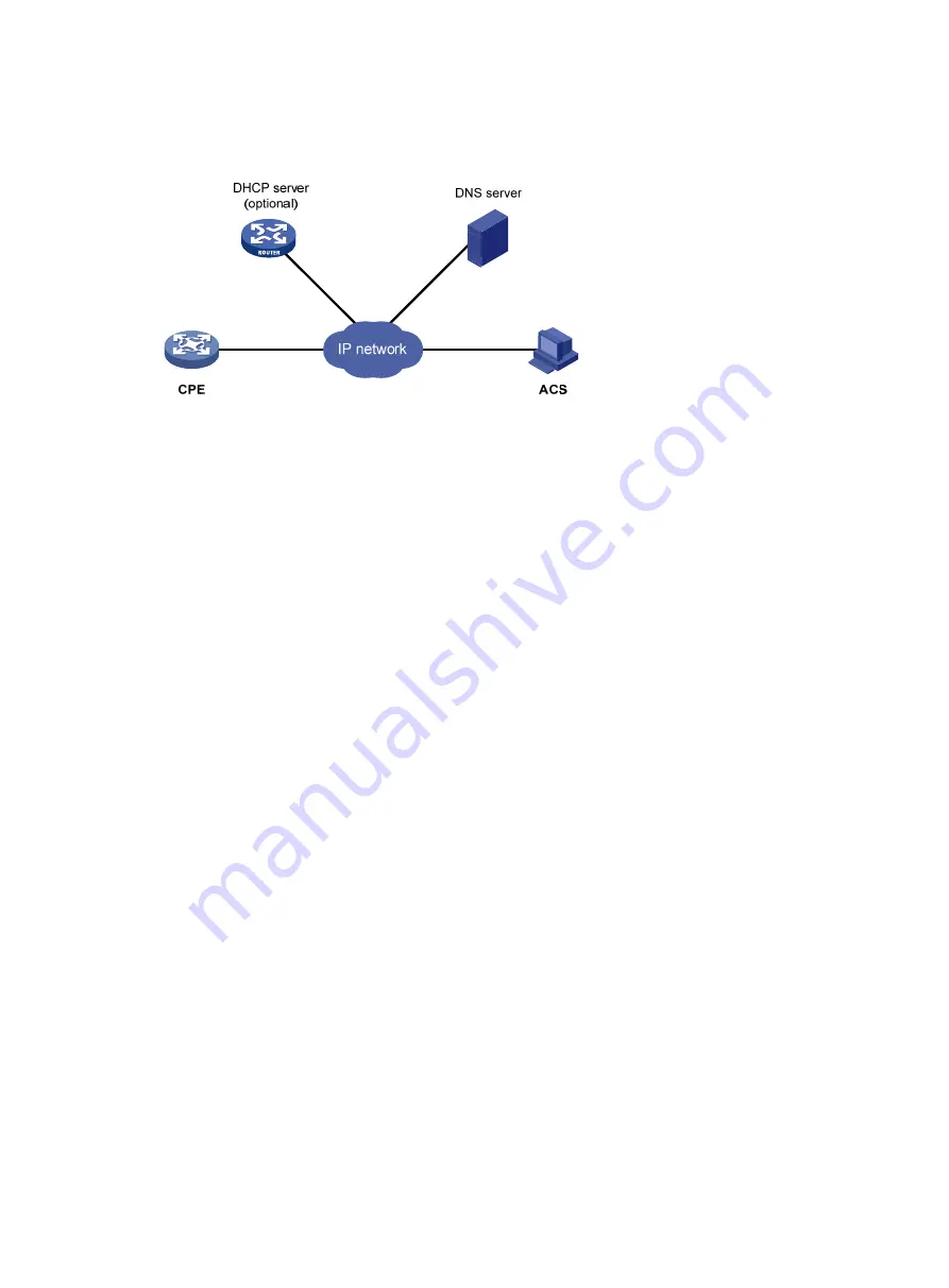
Figure 517
Network diagram
The basic network elements of TR-069 are:
•
ACS
—Auto-Configuration Server, which is the management device in the network.
•
CPE
—Customer Premise Equipment, which is the managed device in the network.
•
DNS server
—Domain Name System server. TR-069 defines that an ACS and a CPE use URLs to
identify and access each other. DNS is used to resolve the URLs.
•
DHCP server
—Dynamic Host Configuration Protocol server, which assigns an IP address to an ACS
and a CPE, and uses the options filed in the DHCP packet to provide configuration parameters to
the CPE.
The MSR router is a CPE and uses TR-069 to communicate with an ACS.
TR-069 basic functions
Auto connection between ACS and CPE
A CPE can connect to an ACS automatically by sending an Inform message. The following conditions
might trigger an auto connection:
•
CPE startup. A CPE can find the corresponding ACS according to the acquired URL, and initiates
a connection to the ACS.
•
A CPE is configured to send Inform messages periodically. The CPE automatically sends an Inform
message at the configured interval (1 hour for example) to establish connections.
•
A CPE is configured to send Inform messages at a specific time. The CPE automatically sends an
Inform message at the configured time to establish a connection.
•
The current session is not finished but interrupted abnormally. In this case, if the number of CPE
auto-connection retries does not reach the limit, the CPE automatically establishes a connection.
An ACS can initiate a Connect Request to a CPE at any time, and can establish a connection with the
CPE after passing the CPE authentication.
Auto-configuration
When a CPE logs in to an ACS, the ACS can automatically apply some configurations to the CPE to
perform auto configuration of the CPE. Auto-configurable parameters supported by the device include,
but are not limited to the following:
•
Configuration file (ConfigFile)
Содержание MSR SERIES
Страница 17: ...xv Documents 835 Websites 835 Conventions 836 Index 838 ...
Страница 20: ...3 Figure 3 Initial page of the Web interface ...
Страница 42: ...25 Figure 13 Firefox Web browser setting ...
Страница 59: ...42 Figure 27 Checking the basic service configuration ...
Страница 73: ...56 Figure 35 Sample interface statistics ...
Страница 156: ...139 Figure 139 Rebooting the 3G modem ...
Страница 168: ...151 Figure 152 Configuring Web server 2 ...
Страница 174: ...157 Figure 158 Configure the URL filtering function ...
Страница 187: ...170 Upon detecting the Land or Smurf attack on Ethernet 0 2 Router outputs an alarm log and drops the attack packet ...
Страница 242: ...225 Figure 233 Enabling the DHCP client on interface Ethernet 0 1 ...
Страница 247: ...230 Figure 236 The page for configuring an advanced IPv4 ACL ...
Страница 255: ...238 Figure 241 Advanced limit setting ...
Страница 298: ...281 e Click Apply 2 Configure Router B in the same way Router A is configured ...
Страница 354: ...337 Figure 339 Configuring a login control rule so Host B cannot access Router through the Web ...
Страница 400: ...383 Figure 387 Verifying the configuration ...
Страница 405: ...388 ...
Страница 523: ...506 Figure 530 Ping configuration page ...
Страница 538: ...521 a Click Device A on the topology diagram b Click Ethernet 0 2 on the panel diagram c Click Port Guard ...
Страница 744: ...727 Verifying the configuration In the case that the IP network is unavailable calls can be made over PSTN ...
Страница 775: ...758 Figure 785 Configuring a jump node ...
Страница 791: ...774 Figure 801 Configuring a jump node ...

