


484
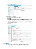
Figure 512
Access level switching page
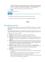
Configuring system time
Configure a correct system time so the device can work with other devices correctly.
The device supports setting and displaying the system time, and setting the time zone and daylight saving
time through manual configuration and automatic synchronization of NTP server time.
An administrator cannot keep time synchronized among all the devices within a network by changing the
system clock on each device, because this is a huge amount of workload and cannot guarantee the clock
precision. NTP, however, allows quick clock synchronization within the entire network and ensures a high
clock precision.
Defined in RFC 1305, NTP synchronizes timekeeping among distributed time servers and clients. NTP
runs over the User Datagram Protocol (UDP), using UDP port 123.
NTP enables you to keep consistent timekeeping among all clock-dependent devices within the network
so that the devices can provide diverse applications based on the consistent time.
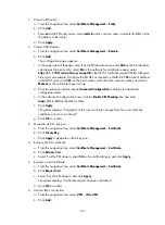
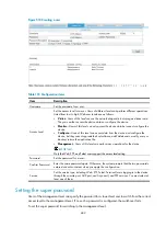
Setting the system time
1.
From the navigation tree, select
System Management
>
System Time
.
The
System Time
page appears. On the upper part of the interface, the current system time is
displayed.
2.
Set the system time as described in
.
3.
Click
Apply
.
Содержание MSR SERIES
Страница 17: ...xv Documents 835 Websites 835 Conventions 836 Index 838 ...
Страница 20: ...3 Figure 3 Initial page of the Web interface ...
Страница 42: ...25 Figure 13 Firefox Web browser setting ...
Страница 59: ...42 Figure 27 Checking the basic service configuration ...
Страница 73: ...56 Figure 35 Sample interface statistics ...
Страница 156: ...139 Figure 139 Rebooting the 3G modem ...
Страница 168: ...151 Figure 152 Configuring Web server 2 ...
Страница 174: ...157 Figure 158 Configure the URL filtering function ...
Страница 187: ...170 Upon detecting the Land or Smurf attack on Ethernet 0 2 Router outputs an alarm log and drops the attack packet ...
Страница 242: ...225 Figure 233 Enabling the DHCP client on interface Ethernet 0 1 ...
Страница 247: ...230 Figure 236 The page for configuring an advanced IPv4 ACL ...
Страница 255: ...238 Figure 241 Advanced limit setting ...
Страница 298: ...281 e Click Apply 2 Configure Router B in the same way Router A is configured ...
Страница 354: ...337 Figure 339 Configuring a login control rule so Host B cannot access Router through the Web ...
Страница 400: ...383 Figure 387 Verifying the configuration ...
Страница 405: ...388 ...
Страница 523: ...506 Figure 530 Ping configuration page ...
Страница 538: ...521 a Click Device A on the topology diagram b Click Ethernet 0 2 on the panel diagram c Click Port Guard ...
Страница 744: ...727 Verifying the configuration In the case that the IP network is unavailable calls can be made over PSTN ...
Страница 775: ...758 Figure 785 Configuring a jump node ...
Страница 791: ...774 Figure 801 Configuring a jump node ...


