


Chapter 3
3-29
Gauging and Making Connections
Making Type-F Connections
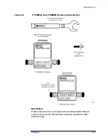
Making Type-F Connections
Good connections require a skilled operator. The most common cause of
measurement error is poor connections.
Typically all precision microwave connectors are designed with an
alignment feature which engages prior to finger insertion to ensure
alignment and support and avoid female finger damage.
The existing SCTE Interface Practices Subcommittee recommended “F”
plug and part does not have any preinsertion alignment features. (See
SCTE IPS-SP-4 and IPS-SP-401.) To avoid female finger failure, the
burden of pin insertion alignment must be sustained by the user. Refer
to
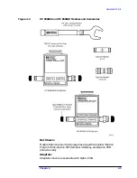
How to Make a Connection
1. Ground yourself and all devices. Wear a grounded wrist strap and
work on an antistatic mat.
2. Visually inspect the connectors.
3. If necessary, clean the connectors.
4. Carefully align the connectors. The male connector center pin must
slip concentrically into the contact fingers of the female connector.
5. Push the connectors straight together. Do not twist or screw them
together. As the center conductors mate, there is usually a slight
resistance.
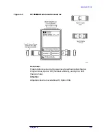
CAUTION
Do not turn the device body. Only turn the connector nut. Major damage
to the center conductor can occur if the device body is twisted.
6. The preliminary connection is tight enough when the mating plane
surfaces make uniform, light contact. Do not overtighten this
connection.
At this point all you want is a connection in which the outer
conductors make gentle contact at all points on both mating
surfaces. Very light finger pressure is enough.
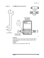
7. Relieve any side pressure on the connection from long or heavy
devices or cables.
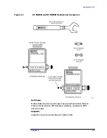
8. Tighten the connector finger-tight. A torque wrench is not included
with the type-F kit. If a torque wrench is needed, use one with a
wrench opening of 12 mm and a torque setting of 170 N-cm.
Содержание HP 85060B
Страница 5: ...1 1 1 General Information ...
Страница 17: ...Chapter 1 1 13 General Information Safety and Regulatory Information ...
Страница 18: ...2 1 2 Specifications and Characteristics ...
Страница 36: ...3 1 3 Gauging and Making Connections ...
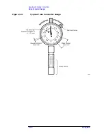
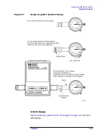
Страница 50: ...Chapter 3 3 15 Gauging and Making Connections Using Connector Gauges Figure 3 2 Typical 3 5 mm Connector Gauge ...
Страница 51: ...3 16 Chapter3 Gauging and Making Connections Using Connector Gauges Figure 3 3 Typical 7 mm Connector Gauge ...
Страница 52: ...Chapter 3 3 17 Gauging and Making Connections Using Connector Gauges Figure 3 4 Typical Type N Connector Gauge ...
Страница 61: ...3 26 Chapter3 Gauging and Making Connections Gauging Techniques Figure 3 8 Using a 3 5 mm Connector Gauge ...
Страница 65: ...3 30 Chapter3 Gauging and Making Connections Making Type F Connections Figure 3 9 Type F Female Connectors ...
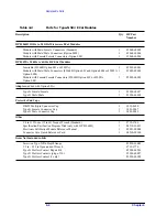
Страница 67: ...4 1 4 Replaceable Parts ...