


2-2
Chapter 2
Specifications and Characteristics
Specifications: Terminology and Definitions
Specifications: Terminology and Definitions
The following terms and definitions are for both RF and microwave
ECal kits. The definitions are intended to help clarify terms used in the
specifications. The definitions are specific to these kits and are not
necessarily valid definitions for other Hewlett-Packard products.
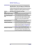
Table 2-1
Specifications and Characteristics Terminology
Terms
Definitions
Operating Temperature Range
This is the temperature range over which the calibration
standards maintain performance to their specifications.
Error-corrected Temperature
Range
This is the allowable vector network analyzer (VNA) ambient
temperature drift during measurement calibration and during
measurements when VNA correction is turned on. It is also the
range over which the VNA maintains its specified performance
while correction is turned on. If this temperature range is
exceeded, the error-corrected performance of the VNA is
degraded.
Measurement Calibration
This calibration determines the corrections necessary for
accuracy-enhanced (correction on) measurements.
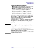
Connector Pin Depth Values
Pin depth is a relative measurement value between the center
conductor and outer conductor mating surfaces. All references to
pin depth in this manual treat positive (+) values as protrusions
of the center conductor, and negative (–) values as recessions of
the center conductor. Refer to
explanation of the measured areas, and
for actual measurement values.
References to Connector Sex
In this manual, adapters, calibration modules, and gauge
masters are referred to by the sex of their connector: a male
adapter has a male connector. A gauge is referred to by the sex of
the connector that it measures: a male gauge measures male
connectors. A male gauge has a corresponding female connector.
Содержание HP 85060B
Страница 5: ...1 1 1 General Information ...
Страница 17: ...Chapter 1 1 13 General Information Safety and Regulatory Information ...
Страница 18: ...2 1 2 Specifications and Characteristics ...
Страница 36: ...3 1 3 Gauging and Making Connections ...
Страница 50: ...Chapter 3 3 15 Gauging and Making Connections Using Connector Gauges Figure 3 2 Typical 3 5 mm Connector Gauge ...
Страница 51: ...3 16 Chapter3 Gauging and Making Connections Using Connector Gauges Figure 3 3 Typical 7 mm Connector Gauge ...
Страница 52: ...Chapter 3 3 17 Gauging and Making Connections Using Connector Gauges Figure 3 4 Typical Type N Connector Gauge ...
Страница 61: ...3 26 Chapter3 Gauging and Making Connections Gauging Techniques Figure 3 8 Using a 3 5 mm Connector Gauge ...
Страница 65: ...3 30 Chapter3 Gauging and Making Connections Making Type F Connections Figure 3 9 Type F Female Connectors ...
Страница 67: ...4 1 4 Replaceable Parts ...