background image

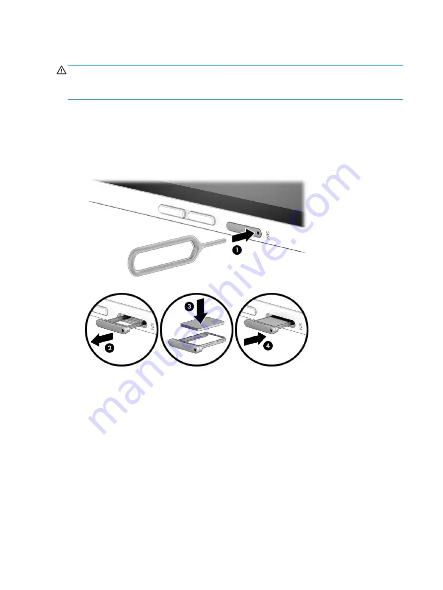
Inserting a nano SIM card 

CAUTION:

To prevent damage to the connectors, use minimal force when inserting a nano SIM card.

CAUTION:

To prevent damage to a SIM card or a computer, do not change the size of a SIM card by cutting or 

sanding the card.

1.

Position the computer display-side up on a flat surface.

2.

Insert the removal tool or a small straightened paper clip (1) into the card tray access hole.

3.

Press the tool or clip in gently until the card tray is ejected.

4.

Remove the tray (2) from the computer and insert the card (3).

5.

Replace the tray in the computer. Press in gently on the tray (4) until it is firmly seated.

To remove a SIM card, reverse the steps.

18

Chapter 2   External component identification

Содержание ENVY x2

Страница 1: ...HP ENVY x2 Detachable model numbers 12 e001 through 12 e099 Maintenance and Service Guide IMPORTANT This document is intended for HP authorized service providers only ...

Страница 2: ...t are common to most models Some features may not be available on your computer Not all features are available in all editions of Windows This computer may require upgraded and or separately purchased hardware drivers and or software to take full advantage of Windows functionality Go to http www microsoft com for details In accordance with Microsoft s support policy HP does not support the Windows...

Страница 3: ... another hard surface such as an adjoining optional printer or a soft surface such as pillows or rugs or clothing to block airflow Also do not allow the AC adapter to contact the skin or a soft surface such as pillows or rugs or clothing during operation The device and the AC adapter comply with the user accessible surface temperature limits defined by the International Standard for Safety of Info...

Страница 4: ...iv Safety warning notice ...

Страница 5: ...rting a nano SIM card 18 Using the microSD memory card reader 19 Inserting a microSD memory card 19 Removing a microSD memory card 20 3 Illustrated parts catalog 21 Computer major components 21 Display assembly subcomponents 24 Miscellaneous parts 25 4 Removal and replacement procedures preliminary requirements 26 Tools required 26 Service considerations 26 Plastic parts 26 Cables and connectors 2...

Страница 6: ... board 46 Power button board 47 Webcams 48 SIM card tray bracket 51 System board 52 MicroSD memory card reader board 55 Speakers 57 6 Using Setup Utility BIOS 59 Starting Setup Utility BIOS 59 Updating Setup Utility BIOS 59 Downloading a BIOS update 59 7 Backing up restoring and recovering 60 Creating backups 60 Restore and recovery 60 8 Using HP PC Hardware Diagnostics UEFI 61 Downloading HP PC H...

Страница 7: ...10 Power cord set requirements 65 Requirements for all countries 65 Requirements for specific countries and regions 66 11 Recycling 68 Index 69 vii ...

Страница 8: ...viii ...

Страница 9: ...video Support for the following integrated cameras Front HP Wide Vision camera high definition 2592 1944 5 MP fixed no tilt wide dynamic range WDR Rear HP Wide Vision camera high definition 4160 3120 13 MP fixed no tilt WDR Triple digital microphone array w appropriate software beam forming echo cancellation noise suppression Dual speakers Bang Olufsen Audio Wireless Qualcomm WCN3990 802 11 AC 2 2...

Страница 10: ...khead style with localized cable plug support 1 meter power cord 3 cell 49 Whr polymer battery Security Qualcomm Mobile Security Solutions Operating system Preinstalled Windows 10 S Serviceability End user replaceable parts AC adapter Soft cover keyboard keyboard cover 2 Chapter 1 Product description ...

Страница 11: ... headset For additional safety information refer to the Regulatory Safety and Environmental Notices To access this guide Select the Start button select HP Help and Support and then select HP Documentation NOTE When a device is connected to the jack the computer speakers are disabled 2 Volume buttons Control speaker volume on the computer 3 Nano SIM card slot Supports a wireless subscriber identity...

Страница 12: ...onnected and the battery has reached a low battery level Amber The AC adapter is connected and the battery is charging Off The battery is not charging 4 USB Type C power connector and SuperSpeed port Connects an AC adapter that has a USB Type C connector supplying power to the computer and if needed charging the computer battery and Connects a USB device that has a Type C connector such as a cell ...

Страница 13: ...Some cameras also allow a facial recognition logon to Windows instead of a password logon NOTE Camera functions vary depending on the camera hardware and software installed on your product The antennas are not visible from the outside of the computer For optimal transmission keep the areas immediately around the antennas free from obstructions For wireless regulatory notices see the section of the...

Страница 14: ...rtion 1 downward from the hinge until it creates a stand at the angle you want 2 Flip the softcover keyboard 2 downward 3 To connect the keyboard lower the computer into the softcover 3 until the connectors click into place 6 Chapter 2 External component identification ...

Страница 15: ...Removing the keyboard 1 To remove the computer from the keyboard pull the keyboard 1 away from the back of the stand 2 Separate the tablet 2 and keyboard 2 Keyboard area 7 ...

Страница 16: ...ger gestures to move the pointer or activate items on the screen 2 Left TouchPad button Functions like the left button on an external mouse 3 Right TouchPad button Functions like the right button on an external mouse 8 Chapter 2 External component identification ...

Страница 17: ...Lights Component Description 1 Caps lock light On Caps lock is on which switches the key input to all capital letters 2 Mute light On Computer sound is off Off Computer sound is on Keyboard area 9 ...

Страница 18: ...ith another key 2 Windows key Opens the Start menu NOTE Pressing the Windows key again will close the Start menu 3 Action keys Execute frequently used system functions NOTE On select products the f5 action key turns the keyboard backlight feature off or on 10 Chapter 2 External component identification ...

Страница 19: ...e computer display to the monitor display to a simultaneous display on both the computer and the monitor Turns the keyboard backlight off or on NOTE To conserve battery power turn off this feature Mutes or restores speaker sound Decreases speaker volume incrementally while you hold down the key Increases speaker volume incrementally while you hold down the key Plays the previous track of an audio ...

Страница 20: ...e computer is in Hibernation press the button briefly to exit Hibernation CAUTION Pressing and holding down the power button results in the loss of unsaved information If the computer has stopped responding and shutdown procedures are ineffective press and hold the power button down for at least 5 seconds to turn off the computer To learn more about your power settings see your power options Right...

Страница 21: ...Bottom Component Description 1 Alignment post connectors 2 Connect to the alignment posts on the keyboard 2 Keyboard connector Connects the computer to the keyboard Bottom 13 ...

Страница 22: ...Rear Component Description 1 Rear internal microphone Records sound 2 Rear camera Allows you to video chat record video and record still images 14 Chapter 2 External component identification ...

Страница 23: ...ess to select an item or perform a right click function NOTE Depending on the application these button functions might vary The button functions cannot be customized For more information about the pen refer to the documentation provided with the pen Also refer to Pen Windows Ink 1 Select Start and then select Settings 2 Select Devices select Pen Windows Ink and then follow the on screen instructio...

Страница 24: ...en store it in the pen holder on the keyboard Make sure to face the buttons toward the computer when storing the pen so as to avoid unintentional activation and battery drain 16 Chapter 2 External component identification ...

Страница 25: ...dentify your computer When contacting support you may be asked for the serial number the product number or the model number Locate this information before you contact support Your service label will contain the information shown below Component 1 IMEI number 2 Model number 3 Product ID 4 HP product name select products only 5 Serial number 6 Warranty period Regulatory label s Provide s regulatory ...

Страница 26: ...tion the computer display side up on a flat surface 2 Insert the removal tool or a small straightened paper clip 1 into the card tray access hole 3 Press the tool or clip in gently until the card tray is ejected 4 Remove the tray 2 from the computer and insert the card 3 5 Replace the tray in the computer Press in gently on the tray 4 until it is firmly seated To remove a SIM card reverse the step...

Страница 27: ...o remove or replace the tray 1 Position the computer display side up on a flat surface 2 Insert the card removal tool or a small straightened paper clip 1 into the card tray access hole 3 Press the tool or clip in gently until the card tray is ejected 4 Remove the tray 2 from the computer and insert the card 3 5 Replace the tray in the computer Press in gently on the tray 4 until it is firmly seat...

Страница 28: ... in the notification area at the far right of the taskbar Then follow the on screen instructions 3 Place the computer display side up on a flat surface 4 Insert the card removal tool or a small straightened paper clip 1 into the card tray access hole 5 Press the tool or clip in gently until the card tray is ejected 6 Remove the tray 2 from the computer and remove the card 3 7 Replace the tray in t...

Страница 29: ...supported parts for your computer go to http partsurfer hp com select your country or region and then follow the on screen instructions NOTE Details about your computer including model serial number product key and length of warranty are on the service tag at the bottom of your computer See Labels on page 17 for details Computer major components 21 ...

Страница 30: ...a wide aspect ratio flush glass panel TouchScreen display assembly L10651 001 2 Touchscreen board L05114 001 3 Battery 3 cell 49 WHr 4 4 AHr Li ion 924961 855 4 USB Type C board L05115 001 5 Touchscreen board cable L05095 001 6 USB Type C cable L05097 001 7 Display panel cable L05102 001 22 Chapter 3 Illustrated parts catalog ...

Страница 31: ...B system memory and a non Windows operating system for use with the 256 GB solid state hard drive L10649 001 Equipped with a Qualcomm Snapdragon 835 Mobile PC processor up to 2 6 GHz eight core processor 1866 MHz FSB 2 0 MB L2 cache a Quallcomm Adreno 540 graphics subsystem 4 GB system memory and the Windows 10 S operating system for use with the 128 GB solid state hard drive L05122 601 Equipped w...

Страница 32: ... part number 1 Touchscreen board L05114 001 2 Display panel 12 3 in WUXGA WLED BrightView 1920 1280 uslim bent 1 96 mm UWVA PSR 3 2 ultra wide aspect ratio flush glass panel TouchScreen display assembly L10651 001 24 Chapter 3 Illustrated parts catalog ...

Страница 33: ...ore processor 1866 MHz FSB 2 0 MB L2 cache a Quallcomm Adreno 540 graphics subsystem 4 GB system memory and a non Windows operating system for use with the 128 GB solid state hard drive in Australia L10650 001 Equipped with a Qualcomm Snapdragon 835 Mobile PC processor up to 2 6 GHz eight core processor 1866 MHz FSB 2 0 MB L2 cache a Quallcomm Adreno 540 graphics subsystem 4 GB system memory and a...

Страница 34: ...ing sections include some of the considerations that you must keep in mind during disassembly and assembly procedures NOTE As you remove each subassembly from the computer place the subassembly and all accompanying screws away from the work area to prevent damage Plastic parts CAUTION Using excessive force during disassembly and reassembly can damage plastic parts Use care when handling the plasti...

Страница 35: ...utions Before removing or inserting a hard drive shut down the computer If you are unsure whether the computer is off or in Hibernation turn the computer on and then shut it down through the operating system Before handling a drive be sure that you are discharged of static electricity While handling a drive avoid touching the connector Before removing an optical drive be sure that a disc is not in...

Страница 36: ...components in their electrostatic safe containers until you are ready to install them Before touching an electronic component discharge static electricity by using the guidelines described in this section Avoid touching pins leads and circuitry Handle electronic components as little as possible If you remove a component place it in an electrostatic safe container The following table shows how humi...

Страница 37: ...to ground and that proper materials are selected to avoid static charging When grounding is not possible use an ionizer to dissipate electric charges Workstation guidelines Follow these grounding workstation guidelines Cover the workstation with approved static shielding material Use a wrist strap connected to a properly grounded work surface and use properly grounded tools and equipment Use condu...

Страница 38: ...tor and ground To be effective the conductive equipment must be worn in contact with the skin The following grounding equipment is recommended to prevent electrostatic damage Antistatic tape Antistatic smocks aprons and sleeve protectors Conductive bins and other assembly or soldering aids Nonconductive foam Conductive tabletop workstations with ground cords of one megohm resistance Static dissipa...

Страница 39: ...rocedures NOTE Details about your computer including model serial number product key and length of warranty are on the service tag at the bottom of your computer See Labels on page 17 for details NOTE HP continually improves and changes product parts For complete and current information on supported parts for your computer go to http partsurfer hp com select your country or region and then follow ...

Страница 40: ...you are unsure whether the tablet is off or in Hibernation turn the tablet on and then shut it down through the operating system 2 Disconnect all external devices connected to the tablet 3 Disconnect the power from the tablet by first unplugging the power cord from the AC outlet and then unplugging the AC adapter from the tablet Remove the display panel assembly 1 Position the tablet with the fron...

Страница 41: ... clear of tools screws and any other foreign objects Failure to follow this caution can result in damage to the display panel assembly 8 Swing the display panel assembly 1 forward until it rests upside down in front of the back cover 9 Release the zero insertion force ZIF connector 2 to which the Touchscreen board cable is connected and then disconnect the Touchscreen board cable from the display ...

Страница 42: ...11 Remove the display panel assembly 6 Reverse this procedure to replace the panel 34 Chapter 5 Removal and replacement procedures ...

Страница 43: ...rst unplugging the power cord from the AC outlet and then unplugging the AC adapter from the tablet 4 Remove the display panel assembly see Display panel assembly on page 32 Remove the Touchscreen board 1 Detach the piece of grounding tape that secures the Touchscreen board 1 to the display panel assembly 2 Release the two ZIF connectors 2 to which the Touchscreen board cables are connected and th...

Страница 44: ... down through the operating system 2 Disconnect all external devices connected to the tablet 3 Disconnect the power from the tablet by first unplugging the power cord from the AC outlet and then unplugging the AC adapter from the tablet 4 Remove the display panel assembly see Display panel assembly on page 32 Remove the battery 1 Remove the graphite tape covering part of the battery and system com...

Страница 45: ...ove the bracket 2 3 Remove the three Phillips PM2 0 2 8 screws that secure the bracket to the enclosure 1 and then remove the bracket 2 4 Disconnect the battery cable 1 from the system board 5 Remove the four Phillips PM2 0 2 0 screws 2 that secure the battery to the back cover Component replacement procedures 37 ...

Страница 46: ...6 Remove the battery 3 Reverse this procedure to install the battery 38 Chapter 5 Removal and replacement procedures ...

Страница 47: ...ablet is off or in Hibernation turn the tablet on and then shut it down through the operating system 2 Disconnect all external devices connected to the tablet 3 Disconnect the power from the tablet by first unplugging the power cord from the AC outlet and then unplugging the AC adapter from the tablet 4 Remove the display panel assembly see Display panel assembly on page 32 and then remove the fol...

Страница 48: ...3 Disconnect the USB Type C board cable from the ZIF connector 5 and then remove the board 6 Reverse this procedure to install the USB Type C board 40 Chapter 5 Removal and replacement procedures ...

Страница 49: ...pter from the tablet 4 Remove the display panel assembly see Display panel assembly on page 32 and then remove the following components Battery see Battery on page 36 Remove the USB Type C cable 1 Remove the two Phillips PM2 0 2 5 screws 1 that secure the bracket to the enclosure and then remove the bracket 2 2 Release the ZIF connectors 3 to which the USB Type C cable is connected and then discon...

Страница 50: ...t 4 Remove the display panel assembly see Display panel assembly on page 32 and then remove the following components Battery see Battery on page 36 Remove the Touchscreen board cable 1 Remove the two Phillips PM2 0 2 5 screws 1 that secure the bracket to the enclosure and then remove the bracket 2 2 Release the ZIF connector 3 to which the Touchscreen board cable is connected and then disconnect t...

Страница 51: ...e AC outlet and then unplugging the AC adapter from the tablet 4 Remove the display panel assembly see Display panel assembly on page 32 and then remove the following components Battery see Battery on page 36 Remove the display panel cable 1 Release the ZIF connector 1 to which the display panel cable is connected and then disconnect the display panel cable from the system board 2 Detach the displ...

Страница 52: ...adapter from the tablet 4 Remove the display panel assembly see Display panel assembly on page 32 and then remove the following components Battery see Battery on page 36 Remove the POGO pin connector cable 1 Disconnect the POGO pin connector cable 1 from the system board 2 Detach the POGO pin connector cable 2 from the back cover The POGO pin connector cable is attached to the back cover with doub...

Страница 53: ... then unplugging the AC adapter from the tablet 4 Remove the display panel assembly see Display panel assembly on page 32 and then remove the following components Battery see Battery on page 36 Remove the audio board 1 Release the ZIF connector attaching the audio board cable to the system board 1 and detach the cable from the back cover the audio board cable is attached to the back cover with dou...

Страница 54: ...ord from the AC outlet and then unplugging the AC adapter from the tablet 4 Remove the display panel assembly see Display panel assembly on page 32 and then remove the following components Battery see Battery on page 36 Remove the volume button board 1 Release the ZIF connector 1 to which the volume button board cable is connected and then disconnect the volume button board cable from the system b...

Страница 55: ...onnect the power from the tablet by first unplugging the power cord from the AC outlet and then unplugging the AC adapter from the tablet 4 Remove the display panel assembly see Display panel assembly on page 32 and then remove the following components Battery see Battery on page 36 Remove the power button board 1 Release the power button board cable from the ZIF connector on the system board 1 an...

Страница 56: ...rst unplugging the power cord from the AC outlet and then unplugging the AC adapter from the tablet 4 Remove the display panel assembly see Display panel assembly on page 32 and then remove the following components Battery see Battery on page 36 Remove the infrared camera 1 Release the ZIF connector 1 to which the infrared camera cable is connected and then disconnect the infrared camera cable fro...

Страница 57: ...he back cover with double sided adhesive 3 Remove the front facing camera 3 from the back cover Remove the rear facing webcam 1 Release the ZIF connector 1 to which the infrared camera cable is connected and then disconnect the infrared camera cable from the system board 2 Detach the rear facing camera 2 from the back cover The infrared camera is attached to the back cover with double sided adhesi...

Страница 58: ...3 Remove the rear facing camera 3 from the back cover Reverse this procedure to install the webcams 50 Chapter 5 Removal and replacement procedures ...

Страница 59: ...from the AC outlet and then unplugging the AC adapter from the tablet 4 Remove the display panel assembly see Display panel assembly on page 32 and then remove the following components a Battery see Battery on page 36 b USB Type C board see USB Type C board on page 39 c Audio board see Audio board on page 45 d Volume button board see Volume button board on page 46 Remove the SIM card tray bracket ...

Страница 60: ...ndows operating system for use with the 128 GB solid state hard drive L05122 001 Before removing the system board follow these steps 1 Shut down the tablet If you are unsure whether the tablet is off or in Hibernation turn the tablet on and then shut it down through the operating system 2 Disconnect all external devices connected to the tablet 3 Disconnect the power from the tablet by first unplug...

Страница 61: ... 10 Ejecting SD card tray 11 Power button board ZIF connector cable 12 Antenna foils 13 Rear facing webcam ZIF connector cable 14 Front facing webcam ZIF connector cable 15 Front microphone cable 16 Infrared webcam cable 17 Infrared webcame LED cable 2 Remove the four Phillips PM2 0 2 0 screws 1 that secure the system board to the back cover Component replacement procedures 53 ...

Страница 62: ...3 Remove the system board 2 Reverse this procedure to install the system board 54 Chapter 5 Removal and replacement procedures ...

Страница 63: ...play panel assembly on page 32 and then remove the following components a Battery see Battery on page 36 b USB Type C board see USB Type C board on page 39 c Audio board see Audio board on page 45 d Volume button board see Volume button board on page 46 e SIM card tray bracket see SIM card tray bracket on page 51 f System board see System board on page 52 Remove the microSD memory card reader boar...

Страница 64: ...Reverse this procedure to install the microSD memory card reader board 56 Chapter 5 Removal and replacement procedures ...

Страница 65: ...apter from the tablet 4 Remove the display panel assembly see Display panel assembly on page 32 and then remove the following components a Battery see Battery on page 36 b USB Type C board see USB Type C board on page 39 c Audio board see Audio board on page 45 d Volume button board see Volume button board on page 46 e SIM card tray bracket see SIM card tray bracket on page 51 f System board see S...

Страница 66: ...4 Rotate the speaker toward the back of the tablet 3 and then remove the speaker 4 Reverse this procedure to install the speakers 58 Chapter 5 Removal and replacement procedures ...

Страница 67: ... is automatically downloaded and installed Downloading a BIOS update CAUTION To reduce the risk of damage to the computer or an unsuccessful installation download and install a BIOS update only when the computer is connected to reliable external power using the AC adapter Do not download or install a BIOS update while the computer is running on battery power docked in an optional docking device or...

Страница 68: ...formation and steps see the Get Help app Select the Start button and then select the Get Help app NOTE You must be connected to the Internet to access the Get Help app 1 Select Start select Settings then select Update security 2 Select Backup and then follow the on screen instructions Restore and recovery Windows offers several options for restoring from backup refreshing the computer and resettin...

Страница 69: ...2 The BIOS searches three places for the diagnostic tools in the following order a Connected USB drive NOTE To download the HP PC Hardware Diagnostics UEFI tool to a USB drive see Downloading the latest HP PC Hardware Diagnostics UEFI version on page 62 b Hard drive c BIOS 3 When the diagnostic tool opens select the type of diagnostic test you want to run and then follow the on screen instructions...

Страница 70: ...test HP PC Hardware Diagnostics UEFI version to a flash drive 1 Go to http www hp com go techcenter pcdiags The HP PC Diagnostics home page is displayed 2 In the HP PC Hardware Diagnostics section select Download and then select Run 62 Chapter 8 Using HP PC Hardware Diagnostics UEFI ...

Страница 71: ...rm The voltage and current for your computer is located on the regulatory label Input power Rating Operating voltage and current 5 V dc 2 A 12 V dc 3 A 15 V dc 3 A 45 W USB C 5 V dc 3 A 9 V dc 3 A 10 V dc 3 75 A 12 V dc 3 75 A 15 V dc 3 A 20 V dc 2 25 A 45 W USB C 5 V dc 3 A 9 V dc 3A 10 V dc 5 A 12 V dc 5 A 15 V dc 4 33 A 20 V dc 3 25 A 65 W USB C 5 V dc 3 A 9 V dc 3 A 10 V dc 5 A 12 V dc 5 A 15 ...

Страница 72: ...5 F Nonoperating 20 C to 60 C 4 F to 140 F Relative humidity noncondensing Operating 10 to 90 10 to 90 Nonoperating 5 to 95 5 to 95 Maximum altitude unpressurized Operating 15 m to 3 048 m 50 ft to 10 000 ft Nonoperating 15 m to 12 192 m 50 ft to 40 000 ft 64 Chapter 9 Specifications ...

Страница 73: ...equirements are applicable to all countries and regions The length of the power cord set must be at least 1 0 m 3 3 ft and no more than 2 0 m 6 5 ft All power cord sets must be approved by an acceptable accredited agency responsible for evaluation in the country or region where the power cord set will be used The power cord sets must have a minimum current capacity of 10 A and a nominal voltage ra...

Страница 74: ...orea KTL 5 Sweden SEMKO 1 Switzerland SEV 1 Taiwan BSMI 6 Thailand TISI 1 The United Kingdom ASTA 1 The United States UL 2 1 The flexible cord must be Type HO5VV F 3 conductor 0 75 mm conductor size Power cord set fittings appliance coupler and wall plug must bear the certification mark of the agency responsible for evaluation in the country or region where it will be used 2 The flexible cord must...

Страница 75: ...e CCC certification mark 5 The flexible cord must be Type H05VV F 3 conductor 0 75 mm conductor size KTL logo and individual approval number must be on each element Corset approval number and logo must be printed on a flag label 6 The flexible cord must be Type HVCTF 3 conductor 1 25 mm conductor size Power cord set fittings appliance coupler cable and wall plug must bear the BSMI certification ma...

Страница 76: ...in general household waste Follow the local laws and regulations in your area for battery disposal HP encourages customers to recycle used electronic hardware HP original print cartridges and rechargeable batteries For more information about recycling programs see the HP Web site at http www hp com recycle 68 Chapter 11 Recycling ...

Страница 77: ... top 12 computer major components 21 connector power 4 D display assembly subcomponents 24 Display panel spare part number 22 24 display panel product description 1 Display panel assembly removal 32 spare part numbers 32 Display panel cable spare part number 22 display panel cable removal 43 spare part number 43 docking connector identifying 13 F fn key identifying 10 Front camera spare part numbe...

Страница 78: ...rd drive 1 keyboard 1 memory module 1 microphone 1 operating system 2 optical drive 1 pointing device 1 ports 1 power requirements 2 processors 1 product name 1 security 2 serviceability 2 video 1 wireless 1 product name 1 product name and number computer 17 R Rear camera spare part number 23 rear microphone identifying 14 rear facing webcam removal 48 spare part number 48 regulatory information r...

Страница 79: ...V video product description 1 Volume button board spare part numbers 23 volume button board removal 46 spare part number 46 W webcam removal 48 spare part numbers 48 Windows system restore point 60 Windows key identifying 10 wireless antennas identifying 5 wireless certification label 17 wireless product description 1 WLAN antennas identifying 5 WLAN device 17 WLAN label 17 WWAN antennas identifyi...

Отзывы: