background image

Bottom cover and rubber feet

Table 5-1

  Bottom cover and rubber feet descriptions and part numbers

Description

Spare part number

Bottom cover in pale gold finish

L94026-001

Bottom cover in natural silver finish

L94027-001

Bottom cover in nightfall black finish

L94028-001

Rubber foot kit for natural silver finish

L94024-001

Rubber foot kit for nightfall black finish

L94025-001

Rubber foot kit for pale gold finish

L94023-001

Prepare the computer for disassembly (

Preparation for disassembly on page 37

).

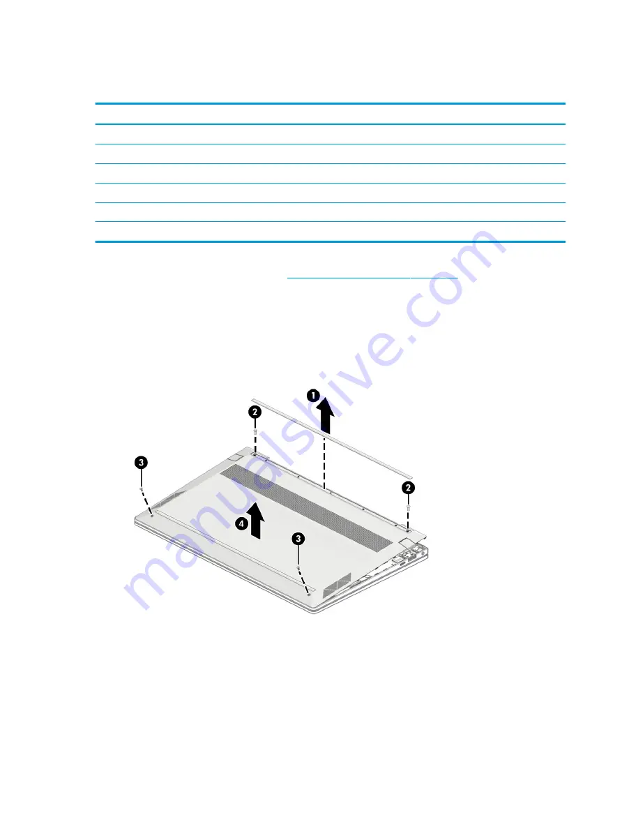
To remove the bottom cover and rubber feet:

1.

Peel the one rubber foot off the bottom of the computer (1).

2.

Remove the two Phillips M2.5 × 5.0 screws from the rear of the computer (2).

3.

Remove the two Phillips M2.5 × 5.0 screws from the front of the computer (3), and then remove the 
bottom cover (4).

Reverse this procedure to install the bottom cover and rubber feet.

38

Chapter 5   Removal and replacement procedures for authorized service provider parts

Содержание ENVY 13

Страница 1: ...Maintenance and Service Guide HP Envy 13 Laptop PC IMPORTANT This document is intended for HP authorized service providers only ...

Страница 2: ...construed as constituting an additional warranty HP shall not be liable for technical or editorial errors or omissions contained herein First Edition April 2020 Document Part Number L98817 001 Product notice This guide describes features that are common to most models Some features may not be available on your computer Not all features are available in all editions or versions of Windows Systems m...

Страница 3: ...a hard flat surface Do not allow another hard surface such as an adjoining optional printer or a soft surface such as pillows or rugs or clothing to block airflow Also do not allow the AC adapter to contact the skin or a soft surface such as pillows or rugs or clothing during operation The computer and the AC adapter comply with the user accessible surface temperature limits defined by applicable ...

Страница 4: ...iv Safety warning notice ...

Страница 5: ...s 15 3 Illustrated parts catalog 17 Computer major components 17 Display assembly subcomponents 27 Mass storage devices 28 Cables 29 Miscellaneous parts 30 4 Removal and replacement procedures preliminary requirements 32 Tools required 32 Service considerations 32 Plastic parts 32 Cables and connectors 32 Drive handling 33 Workstation guidelines 33 Electrostatic discharge information 33 Generating...

Страница 6: ...y media 64 Using Windows tools 64 Using the HP Cloud Recovery Download Tool to create recovery media select products only 64 Restoring and recovery 65 Restoring resetting and refreshing using Windows tools 65 Recovering using HP Recovery media 65 Changing the computer boot order 65 Using HP Sure Recover select products only 66 7 Using HP PC Hardware Diagnostics 67 Using HP PC Hardware Diagnostics ...

Страница 7: ... Remote HP PC Hardware Diagnostics UEFI 70 Downloading the latest Remote HP PC Hardware Diagnostics UEFI version 70 Downloading Remote HP PC Hardware Diagnostics UEFI by product name or number 70 Customizing Remote HP PC Hardware Diagnostics UEFI settings 70 8 Specifications 72 Computer specifications 72 xx cm xx in display specifications 73 Hard drive specifications 73 9 Power cord set requiremen...

Страница 8: ...viii ...

Страница 9: ...LED 3 8 mm Full high definition FHD 1920 1080 WLED UWVA 72 1000 eDP 1 4 PSR2 with Privacy FHD 1920 1080 WLED UWVA 72 300 eDP 1 3 PSR nontouch screen FG DBCG FHD 1920 1080 WLED UWVA 72 300 eDP 1 3 PSR Touch screen DBTS VBM FHD 1920 1080 WLED UWVA sRGB 100 400 eDP 1 4 PSR2 TS LP DBTS VBM FHD 1920 1080 WLED UWVA sRGB 100 400 eDP 1 4 PSR2 nontouch FG LP DBTS VBM UHD 3840 2160 WLED UWVA HDR 400 sRGB 95...

Страница 10: ...1ax 2 2 MU MIMO supporting gigabit file transfer speeds Ports HP Smart Plug AC adapter Audio out headphone Audio in microphone combo jack Hot plug unplug and autodetect for correct output to wide aspect vs standard aspect video auto adjust panel resolution to fit embedded panel and external monitor connected USB 3 2 Gen1 Type A 2 USB 3 2 Gen 2 Type C port 1 Media card reader Supports HP MultiForma...

Страница 11: ...system Preinstalled Windows Win 10 Home 64 Win 10 Home 64 Advanced Win 10 Home 64 Advanced Single Language Win 10 Home 64 High End Chinese Market CPPP Win 10 Home 64 Plus Win 10 Home 64 Plus Single Language Win 10 Home 64 Plus Single Language Africa Market PPP Win 10 Home 64 Plus Single Language APAC EM PPP Win 10 Home 64 Plus Single Language India Market PPP Win 10 Home 64 Plus Single Language In...

Страница 12: ...ut what hardware is installed on your computer Type device manager in the taskbar search box and then select the Device Manager app A list displays all the devices installed on your computer For information about system hardware components and the system BIOS version number press fn esc select products only Locating software Software can vary by product To find out what software is installed on yo...

Страница 13: ...o remove a card Press in on the card and then remove it from the memory card reader 2 USB port with HP Sleep and Charge Connects a USB device provides high speed data transfer and charges small devices even when the computer is off 3 AC adapter and battery light White The AC adapter is connected and the battery is fully charged Blinking white select products only The AC adapter is disconnected and...

Страница 14: ...he computer speakers are disabled 2 USB port Connects a USB device provides data transfer and for select products charges small devices even when the computer is on or in Sleep mode 3 USB Type C port with HP Sleep and Charge select products only Connects a USB device provides data transfer and charges small devices even when the computer is off and Connects a display device that has a USB Type C c...

Страница 15: ...nt Description 1 WLAN antennas Send and receive wireless signals to communicate with wireless local area networks WLANs 2 Internal microphones Record sound 3 Camera Allows you to video chat record video and record still images Some cameras also allow a facial recognition logon to Windows instead of a password logon NOTE To turn the camera on or off press the camera privacy key When the camera is t...

Страница 16: ...n For wireless regulatory notices see the section of the Regulatory Safety and Environmental Notices that applies to your country or region To access this guide Type HP Documentation in the taskbar search box and then select HP Documentation 8 Chapter 2 Getting to know your computer ...

Страница 17: ...ress enter 2 Using an external mouse click the touchpad button or Press the Tab key repeatedly until the pointer rests on the touchpad button Then press the spacebar to select the button Table 2 4 Touchpad components and their descriptions Component Description 1 Touchpad zone Reads your finger gestures to move the pointer or activate items on the screen 2 Left touchpad button Functions like the l...

Страница 18: ...phone is on 4 Camera privacy light On The camera is off Off The camera is on 5 Power light On The computer is on Blinking select products only The computer is in the Sleep state a power saving state The computer shuts off power to the display and other unnecessary components Off Depending on your computer model the computer is off in Hibernation or in Sleep Hibernation is the power saving state th...

Страница 19: ...n Hibernation press the button briefly to exit Hibernation IMPORTANT Pressing and holding down the power button results in the loss of unsaved information If the computer has stopped responding and shutdown procedures are ineffective press and hold the power button down for at least 10 seconds to turn off the computer To learn more about your power settings see your power options Right click the P...

Страница 20: ...r descriptions continued Component Description IMPORTANT To prevent fingerprint logon issues be sure when you register your fingerprint that all sides of your finger are registered by the fingerprint reader 12 Chapter 2 Getting to know your computer ...

Страница 21: ... f12 keys The action keys vary by computer 5 Fingerprint reader Allows a fingerprint logon to Windows instead of a password logon Touch your finger to the fingerprint reader IMPORTANT To prevent fingerprint logon issues be sure when you register your fingerprint that all sides of your finger are registered by the fingerprint reader 6 Camera privacy key Turns the camera off and on 7 Power button Wh...

Страница 22: ... button down for at least 10 seconds to turn off the computer To learn more about your power settings see your power options Right click the Power icon and then select Power Options Bottom Table 2 8 Bottom components and their descriptions Component Description 1 Vent Enables airflow to cool internal components NOTE The computer fan starts up automatically to cool internal components and prevent o...

Страница 23: ...ttom of a tablet kickstand Service label Provides important information to identify your computer When contacting support you might be asked for the serial number the product number or the model number Locate this information before you contact support Your service label will resemble one of the following examples Refer to the illustration that most closely matches the service label on your comput...

Страница 24: ...atory label s Provide s regulatory information about the computer Wireless certification label s Provide s information about optional wireless devices and the approval markings for the countries or regions in which the devices have been approved for use 16 Chapter 2 Getting to know your computer ...

Страница 25: ... information about supported parts for your computer go to http partsurfer hp com select your country or region and then follow the on screen instructions NOTE Details about your computer including model serial number product key and length of warranty are on the service tag at the bottom of your computer Computer major components 17 ...

Страница 26: ...ilver finish nontouch screen L96778 001 FHD pale gold finish nontouch screen L96779 001 FHD nightfall black finish nontouch screen L96780 001 FHD natural silver finish touch screen L96781 001 FHD pale gold finish touch screen L96782 001 FHD nightfall black finish touch screen L96783 001 18 Chapter 3 Illustrated parts catalog ...

Страница 27: ...r finish with backlight L96799 001 For use in the United Kingdom in natural silver finish with backlight L96799 031 For use in Germany in natural silver finish with backlight L96799 041 For use in France in natural silver finish with backlight L96799 051 For use in Italy in natural silver finish with backlight L96799 061 For use in Portugal in natural silver finish with backlight L96799 131 For us...

Страница 28: ...ugal in natural silver finish with backlight and privacy L96800 131 For use in Turkey in natural silver finish with backlight and privacy L96800 141 For use in Greece in natural silver finish with backlight and privacy L96800 151 For use in Saudi Arabia in natural silver finish with backlight and privacy L96800 171 For use in Hungary in natural silver finish with backlight and privacy L96800 211 F...

Страница 29: ...96801 261 For use in Romania in natural silver finish with backlight L96801 271 For use in Thailand in natural silver finish with backlight L96801 281 For use in Belgium in natural silver finish with backlight L96801 A41 For use in Taiwan in natural silver finish with backlight L96801 AB1 For use in Korea in natural silver finish with backlight L96801 AD1 For International use in natural silver fi...

Страница 30: ...d privacy L96802 B31 For use in Slovenia in natural silver finish with backlight and privacy L96802 BA1 For use in Israel in natural silver finish with backlight and privacy L96802 BB1 For use in Ukraine in natural silver finish with backlight and privacy L96802 BD1 For use in Switzerland in natural silver finish with backlight and privacy L96802 BG1 For use in French Canada in natural silver fini...

Страница 31: ...inish with backlight L96803 DH1 For use in the Czech Republic and Slovakia in pale gold finish with backlight L96803 FL1 For use in the United States in pale gold finish with backlight L96804 001 For use in the United Kingdom in pale gold finish with backlight L96804 031 For use in Germany in pale gold finish with backlight L96804 041 For use in France in pale gold finish with backlight L96804 051...

Страница 32: ...light L96805 AB1 For use in Korea with wood veneer and backlight L96805 AD1 For use in French Canada with wood veneer and backlight L96805 DB1 For use in the United States with wood veneer backlight and privacy L96806 001 For use in the United Kingdom with wood veneer backlight with privacy L96806 031 For use in Germany with wood veneer backlight with privacy L96806 041 For use in France with wood...

Страница 33: ...ivacy L96808 031 For use in Germany with wood veneer backlight and privacy L96808 041 For use in France with wood veneer backlight and privacy L96808 051 For use in Italy with wood veneer backlight and privacy L96808 061 For use in Spain with wood veneer backlight and privacy L96808 071 For use in Portugal with wood veneer backlight and privacy L96808 131 For use in Turkey with wood veneer backlig...

Страница 34: ...MA graphics memory L94590 601 Intel Core i7 1065 G7 processor and 8 GB of UMA graphics memory L94591 601 Intel Core i5 1021 U8 processor and 2 GB of discrete graphics memory L94592 601 Intel Core i7 1051 U8 processor and 2 GB of discrete graphics memory L94593 601 Intel Core i7 1051 U16 processor and 2 GB of discrete graphics memory L94594 601 9 Fan L94043 001 10 Heat sink Thermal module for model...

Страница 35: ...part number 1 Display panel FHD natural silver finish nontouch screen L96778 001 FHD pale gold finish nontouch screen L96779 001 FHD nightfall black finish nontouch screen L96780 001 FHD natural silver finish touch screen L96781 001 FHD pale gold finish touch screen L96782 001 FHD nightfall black finish touch screen L96783 001 FHD natural silver finish nontouch screen L96784 001 FHD pale gold fini...

Страница 36: ...FHD nightfall black finish touch screen with privacy L96795 001 UHD natural silver finish touch screen L96796 001 UHD pale gold finish touch screen L96797 001 UHD nightfall black finish touch screen L96798 001 2 Camera L94059 001 3 Display panel cable Display panel cable for FHD screen L94071 001 Display panel cable for UHD screen L94056 001 4 Hinge kit L94049 001 5 Touch screen board select produ...

Страница 37: ...85350 005 256 GB PCIe value L85354 005 32 GB 512 GB PCIe NVMe 3 4 TLC SS Optane memory module solid state drive combination drive L85366 005 16 GB PCIe NVMe Value Optane memory module L85356 005 2 USB optical disk drive external 747080 005 Cables Table 3 4 Cables and their descriptions Component Spare part number 1 IR sensor cable L94040 001 2 Touchpad cable L94032 001 3 Display panel cable FHD di...

Страница 38: ...traight C5 1 0 m For use in Denmark L22322 001 For use in Europe L22321 001 For use in Israel L22323 001 For use in North America L22319 001 For use in South Africa L22325 001 For use in Switzerland L22324 001 For use in the United Kingdom L22320 001 For use in Japan 226768 001 L22330 001 For use in China L21930 001 For use in Thailand L22326 001 For use in Australia L22327 001 For use in Korea L2...

Страница 39: ... C to USB A 916838 001 Adapter HP USB C to RJ45 855560 001 Adapter USB C to HDMI 2 0 935325 001 Adapter USB C to USB A cable adapter 833960 001 Screw kit L94062 001 Rubber kit USB door for natural silver finish L94030 001 Rubber kit USB door for pale gold finish L94029 001 Rubber kit USB door for nightfall black finish L94031 001 Hinge kit L94049 001 Miscellaneous parts 31 ...

Страница 40: ...ive force during disassembly and reassembly can damage plastic parts Cables and connectors IMPORTANT When servicing the computer be sure that cables are placed in their proper locations during the reassembly process Improper cable placement can damage the computer Cables must be handled with extreme care to avoid damage Apply only the tension required to unseat or seat the cables during removal an...

Страница 41: ...the workstation with approved static shielding material Use a wrist strap connected to a properly grounded work surface and use properly grounded tools and equipment Use conductive field service tools such as cutters screw drivers and vacuums When fixtures must directly contact dissipative surfaces use fixtures made only of static safe materials Keep the work area free of nonconductive materials s...

Страница 42: ...oving DIPs from vinyl tray Removing DIPs from polystyrene foam Removing bubble pack from PCB printed circuit board Packing PCBs in foam lined box 2 000 V 3 500 V 7 000 V 5 000 V 4 000 V 5 000 V 20 000 V 11 000 V 11 500 V 14 500 V 26 500 V 21 000 V Multiple electric components can be packaged together in plastic tubes trays or polystyrene foam NOTE As little as 700 V can degrade a product Preventin...

Страница 43: ...the work area To prevent static damage at the work area use the following precautions Cover the work surface with approved static dissipative material Provide a wrist strap connected to the work surface and properly grounded tools and equipment Use static dissipative mats foot straps or air ionizers to give added protection Handle electrostatic sensitive components parts and assemblies by the case...

Страница 44: ...s and assemblies with conductive or approved containers or packaging Keep ESD sensitive parts in their containers until the parts arrive at static free workstations Place items on a grounded surface before removing items from their containers Always be properly grounded when touching a component or assembly Store reusable ESD sensitive parts from assemblies in protective packaging or nonconductive...

Страница 45: ...acement procedures There are as many as 52 screws that must be removed replaced or loosened when servicing the parts described in this chapter Make special note of each screw size and location during removal and replacement Preparation for disassembly See Removal and replacement procedures preliminary requirements on page 32 for initial safety procedures 1 Turn off the computer If you are unsure w...

Страница 46: ...025 001 Rubber foot kit for pale gold finish L94023 001 Prepare the computer for disassembly Preparation for disassembly on page 37 To remove the bottom cover and rubber feet 1 Peel the one rubber foot off the bottom of the computer 1 2 Remove the two Phillips M2 5 5 0 screws from the rear of the computer 2 3 Remove the two Phillips M2 5 5 0 screws from the front of the computer 3 and then remove ...

Страница 47: ...ssembly Preparation for disassembly on page 37 2 Remove the bottom cover see Bottom cover and rubber feet on page 38 To remove the battery 1 Disconnect the battery cable from the computer 1 2 Remove the six Phillips M2 0 6 0 screws 2 that secure the battery to the computer 3 Remove the battery from the computer 3 Reverse this procedure to install the battery Component replacement procedures 39 ...

Страница 48: ...mputer for disassembly Preparation for disassembly on page 37 2 Remove the bottom cover see Bottom cover and rubber feet on page 38 3 Remove the battery see Battery on page 39 To remove the touchpad 1 Disconnect the touchpad cable from the touchpad connector on the system board 1 2 Remove the two Phillips M1 6 3 0 screws 2 and the two Phillips M1 6 2 0 screws 3 that secure the touchpad bracket to ...

Страница 49: ...Reverse this procedure to install the touchpad Component replacement procedures 41 ...

Страница 50: ...Bottom cover and rubber feet on page 38 3 Remove the battery see Battery on page 39 4 Remove the touchpad see Touchpad on page 40 To remove the speakers 1 Disconnect the speaker cable 1 2 Remove the four Phillips M2 0 2 0 screws that secure the speakers to the computer 3 Detach the left and right speaker cables from the clips holding them 3 4 Remove the speaker assembly 4 Reverse this procedure to...

Страница 51: ...te drive combination drive L85372 005 1 TB M2 2280 PCIe NVMe Value L85370 005 1 TB M2 2280 PCIe NVMe 3 4 TLC SS L85348 005 Before removing the solid state drive follow these steps 1 Prepare the computer for disassembly Preparation for disassembly on page 37 2 Remove the bottom cover see Bottom cover and rubber feet on page 38 3 Remove the battery see Battery on page 39 To remove the solid state dr...

Страница 52: ...d state drive bracket 3 3 Remove the Phillips M2 0 3 0 screw 1 lift the solid state drive module bracket and pull the solid state drive module from the socket 2 Reverse this procedure to install the solid state drive 44 Chapter 5 Removal and replacement procedures for authorized service provider parts ...

Страница 53: ...on your model Before removing the WLAN module follow these steps 1 Prepare the computer for disassembly Preparation for disassembly on page 37 2 Remove the bottom cover see Bottom cover and rubber feet on page 38 3 Remove the battery see Battery on page 39 To remove the WLAN module NOTE On select products the size and shape of the Mylar cover may vary from the illustration 1 Pull back the Mylar co...

Страница 54: ...e the WLAN module 4 by pulling the module away from the slot at an angle Reverse this procedure to install the WLAN module 46 Chapter 5 Removal and replacement procedures for authorized service provider parts ...

Страница 55: ...r feet on page 38 3 Remove the battery see Battery on page 39 To remove the fan NOTE On select products the size and shape of the Mylar cover may vary from the illustration 1 Pull back the Mylar cover to access the fan 1 2 Disconnect the fan cable from the system board 2 3 Remove the two Phillips M2 0 2 0 screws 3 that secure the fan to the computer 4 Remove the fan from the computer 4 Reverse thi...

Страница 56: ...m cover see Bottom cover and rubber feet on page 38 3 Remove the battery see Battery on page 39 4 Remove the fan Remove the heat sink on models with discrete graphics 1 Remove the six Phillips M2 0 3 0 screws 1 that secure the heat sink to the system board 2 Remove the heat sink 2 Remove the heat sink on models with UMA graphics 1 Remove the three Phillips M2 0 2 0 screws 1 that secure the heat si...

Страница 57: ...2 Remove the heat sink Reverse this procedure to install the heat sink Component replacement procedures 49 ...

Страница 58: ...035 G1 processor and 8 GB of UMA graphics memory L94589 601 Before removing the system board follow these steps 1 Prepare the computer for disassembly Preparation for disassembly on page 37 2 Remove the bottom cover see Bottom cover and rubber feet on page 38 3 Remove the battery see Battery on page 39 4 Remove the solid state drive see Solid state drive and Optane Memory Module on page 43 To remo...

Страница 59: ... 0 3 0 screws 1 and then remove the USB Type C bracket securing the system board 2 3 Remove the four M2 0 3 0 screws securing the system board 3 Lift the system board 1 and then remove the board 2 Component replacement procedures 51 ...

Страница 60: ...assembly Preparation for disassembly on page 37 2 Remove the bottom cover see Bottom cover and rubber feet on page 38 3 Remove the battery see Battery on page 39 4 Remove the heat sink see Heat sink on page 48 5 Remove the system board see System board on page 50 To remove the IR sensor board 1 Remove the IR sensor board M2 0 1 0 screw from the IR board 1 52 Chapter 5 Removal and replacement proce...

Страница 61: ...2 Remove the IR board from the computer 2 Reverse this procedure to install the IR sensor board Component replacement procedures 53 ...

Страница 62: ...ouch screen with privacy L96791 001 FHD nightfall black finish nontouch screen with privacy L96792 001 FHD natural silver finish touch screen with privacy L96793 001 FHD pale gold finish touch screen with privacy L96794 001 FHD nightfall black finish touch screen with privacy L96795 001 UHD natural silver finish touch screen L96796 001 FHD pale gold finish touch screen L96797 001 Display assembly ...

Страница 63: ...nnect the display panel cable on the right side 3 and remove the cable 4 4 Remove the two Phillips M2 0 3 0 screws 1 from each hinge 5 Open the display to open the hinges 2 Component replacement procedures 55 ...

Страница 64: ...ssis 3 Reverse this procedure to install the display assembly 7 Position two suction cup tools at the illustrated location on the display panel 1 and then rotate each locking lever down to lock the cup 2 56 Chapter 5 Removal and replacement procedures for authorized service provider parts ...

Страница 65: ...t attempt to pry the panel off the enclosure Doing so might break the panel To avoid tearing the tape do not pull on it with the sharp end of tweezers NOTE To fully remove the panel repeat the above procedure on the other side Be sure not to use suction cups in the middle to avoid damaging the camera module 9 Use the following steps to install a display panel a Download and install the touch panel...

Страница 66: ...ed tape so it can be secured to the rear 3 e Place the panel on top of the display panel cover 1 and then press the panel down to secure it to the display enclosure 2 58 Chapter 5 Removal and replacement procedures for authorized service provider parts ...

Страница 67: ...era from the display panel cover 4 and then remove the camera 5 To release the camera cable from the camera connector lift the release arm on the camera connector securing the camera cable to the connector 1 and then release the camera cable 2 Reverse this procedure to install the camera and the camera cable The camera is available as spare part number L87982 001 Component replacement procedures 5...

Страница 68: ...elease the adhesive tape from the touch screen board 3 and then remove the touch screen board after releasing it from the clips securing it The touch screen board is available as spare part number L87966 001 and the touch screen board cable is available as spare part number L87956 001 The touch screen board in included in the touch panel kit 60 Chapter 5 Removal and replacement procedures for auth...

Страница 69: ...na 2 and disengage the cable from the clips that secure the antenna cable to the display enclosure 3 The separate antenna is available as spare part number L94057 001 The antenna that is included with the back cover is available in natural silver finish L94046 001 in nightfall black finish L94046 001 and pale gold finish L94046 001 Component replacement procedures 61 ...

Страница 70: ...assembly on page 37 2 Remove the bottom cover see Bottom cover and rubber feet on page 38 3 Remove the battery see Battery on page 39 To remove the power connector 1 Pull back the Mylar cover to access the power connector 1 2 Remove the cable 2 3 Remove the power connector and cable from the computer 3 Reverse this procedure to install the power connector cable 62 Chapter 5 Removal and replacement...

Страница 71: ...3 xx1 Keyboard top cover with touchpad and nightfall black finish with wood veneer with backlight NOTE Touchpad cannot be replaced L96805 xx1 Table 5 13 Keyboard country codes For use in country or region Spare part number For use in country or region Spare part number For use in country or region Spare part number Belgium A41 Israel BB1 Slovenia BA1 Czech Republic and Slovakia FL1 Italy 061 Spain...

Страница 72: ...recovery process IMPORTANT For a tablet with a detachable keyboard connect the tablet to the keyboard base before beginning any recovery process Backing up information and creating recovery media Using Windows tools IMPORTANT Windows is the only option that allows you to back up your personal information Schedule regular backups to avoid information loss You can use Windows tools to back up person...

Страница 73: ... on screen instructions To recover your system Insert the HP Recovery media and then restart the computer Changing the computer boot order If your computer does not restart using the HP Recovery media you can change the computer boot order This is the order of devices listed in BIOS where the computer looks for startup information You can change the selection to an optical drive or a USB flash dri...

Страница 74: ...lled recovery software Using HP Sure Recover an administrator or user can restore the system and install Latest version of the operating system Platform specific device drivers Software applications in the case of a custom image To access the latest documentation for HP Sure Recover go to http www hp com support Select Find your product and then follow the on screen instructions 66 Chapter 6 Backi...

Страница 75: ...C Hardware Diagnostics Windows from HP Support Assistant a Type support in the taskbar search box and then select the HP Support Assistant app or Select the question mark icon in the taskbar b Select Troubleshooting and fixes c Select Diagnostics and then select HP PC Hardware Diagnostics Windows 2 When the tool opens select the type of diagnostic test that you want to run and then follow the on s...

Страница 76: ...t your type of product and then enter the product name or number in the search box that is displayed 3 In the Diagnostics section select Download and then follow the on screen instructions to select the specific Windows diagnostics version to be downloaded to your computer or USB flash drive The tool downloads to the selected location Installing HP PC Hardware Diagnostics Windows To install HP PC ...

Страница 77: ...onnected USB flash drive NOTE To download the HP PC Hardware Diagnostics UEFI tool to a USB flash drive see Downloading the latest HP PC Hardware Diagnostics UEFI version on page 69 b Hard drive c BIOS 3 When the diagnostic tool opens select a language select the type of diagnostic test you want to run and then follow the on screen instructions Downloading HP PC Hardware Diagnostics UEFI to a USB ...

Страница 78: ...Diagnostics UEFI NOTE HP Remote PC Hardware Diagnostics UEFI is also available as a SoftPaq that you can download to a server Downloading the latest Remote HP PC Hardware Diagnostics UEFI version To download the latest Remote HP PC Hardware Diagnostics UEFI version follow these steps 1 Go to http www hp com go techcenter pcdiags The HP PC Diagnostics home page is displayed 2 Select Download Remote...

Страница 79: ...emote diagnostics Set a location for storing the test results You can also set the user name and password that you use for uploads Display status information about the diagnostics run previously To customize Remote HP PC Hardware Diagnostics UEFI settings follow these steps 1 Turn on or restart the computer and when the HP logo appears press f10 to enter Computer Setup 2 Select Advanced and then s...

Страница 80: ...4 62 A 90 W 19 5 V dc 2 31 45 W select models only Temperature Operating 5 C to 35 C 41 F to 95 F Nonoperating 20 C to 60 C 4 F to 140 F Relative humidity noncondensing Operating 10 to 90 Nonoperating 5 to 95 Maximum altitude unpressurized Operating 15 m to 3 048 m 05 ft to 10 000 ft Nonoperating 15 m to 12 192 m 50 ft to 40 000 ft NOTE Applicable product safety standards specify thermal limits fo...

Страница 81: ...ght LED Character display 80 25 Total power consumption 2 0 W Viewing angle 65 horizontal 50 vertical typical Hard drive specifications Table 8 3 Hard drive specifications 500 GB 750 GB Dimensions Height 9 5 mm 9 5 mm Width 70 mm 70 mm Weight 107 g max 102 g max Interface type SATA SATA Transfer rate 300 MB s 300 MB s Security ATA security ATA security Seek times typical read including setting Sin...

Страница 82: ... Operating temperature 0 C to 60 C 0 F to 140 F 0 C to 60 C 0 F to 140 F Size refers to hard drive storage capacity Actual accessible capacity is less Actual drive specifications may differ slightly NOTE Certain restrictions and exclusions apply Contact support for details 74 Chapter 8 Specifications ...

Страница 83: ...equirements are applicable to all countries and regions The length of the power cord set must be at least 1 0 m 3 3 ft and no more than 2 0 m 6 5 ft All power cord sets must be approved by an acceptable accredited agency responsible for evaluation in the country or region where the power cord set will be used The power cord sets must have a minimum current capacity of 10 A and a nominal voltage ra...

Страница 84: ...JIS 3 The Netherlands KEMA 1 New Zealand SANZ 1 Norway NEMKO 1 The People s Republic of China CCC 4 Saudi Arabia SASO 7 Singapore PSB 1 South Africa SABS 1 South Korea KTL 5 Sweden SEMKO 1 Switzerland SEV 1 Taiwan BSMI 6 Thailand TISI 1 The United Kingdom ASTA 1 The United States UL 2 1 The flexible cord must be Type HO5VV F 3 conductor 0 75 mm conductor size Power cord set fittings appliance coup...

Страница 85: ...303 7 A 125 V ac configuration 4 The flexible cord must be Type RVV 3 conductor 0 75 mm conductor size Power cord set fittings appliance coupler and wall plug must bear the CCC certification mark 5 The flexible cord must be Type H05VV F 3 conductor 0 75 mm conductor size KTL logo and individual approval number must be on each element Approval number and logo must be printed on a flag label 6 The f...

Страница 86: ...in general household waste Follow the local laws and regulations in your area for battery disposal HP encourages customers to recycle used electronic hardware HP original print cartridges and rechargeable batteries For more information about recycling programs see the HP Web site at http www hp com recycle 78 Chapter 10 Recycling ...

Страница 87: ...cations 73 display assembly removal 54 subcomponents 27 display components 7 display panel product description 1 spare part number 27 display panel cable spare part number 28 E electrostatic discharge ESD 33 preventing damage 34 esc key identifying 13 F fan removal 47 spare part number 47 fans spare part numbers 26 fingerprint reader identifying 11 13 fn key identifying 13 G graphics product descr...

Страница 88: ...ption audio 2 display panel 1 graphics 1 hard drive 1 keyboard 2 memory module 1 microphone 2 operating system 3 pointing device 2 ports 2 power requirements 2 processors 1 product name 1 security 3 serviceability 3 video 2 wireless 2 product name 1 product name and number computer 15 R recovery 64 discs 65 HP Recovery partition 65 media 65 USB flash drive 65 recovery media creating using HP Cloud...

Страница 89: ...fying 6 USB Type C port with HP Sleep and Charge identifying 6 USB Type C Thunderbolt port with HP Sleep and Charge identifying 6 V vents identifying 14 video 2 video product description 2 W Windows backup 64 recovery media 64 system restore point 64 Windows key identifying 13 Windows tools using 64 wireless certification label 16 wireless product description 2 WLAN antennas identifying 7 WLAN dev...

Отзывы: