background image

2

External component identification

Your computer features top-rated components. This chapter provides details about your components, where 
they're located, and how they work.

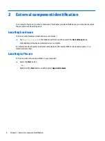
Locating hardware

To find out what hardware is installed on your computer:

Type 

device manager

 in the taskbar search box, and then select the Device Manager app.

A list displays all the devices installed on your computer.

For information about system hardware components and the system BIOS version number, press 

fn

+

esc 

(select products only).

Locating software

To find out what software is installed on your computer:

Select the Start button.

 or –

Right-click the Start button, and then select Apps and Features.

6

Chapter 2   External component identification

Содержание EliteBook 1040 G4

Страница 1: ...HP EliteBook 1040 G4 Notebook PC Maintenance and Service Guide IMPORTANT This document is intended for HP authorized service providers only ...

Страница 2: ...ional warranty HP shall not be liable for technical or editorial errors or omissions contained herein First Edition September 2017 Document Part Number L00437 001 Product notice This user guide describes features that are common to most models Some features may not be available on your computer Not all features are available in all editions of Windows This computer may require upgraded and or sepa...

Страница 3: ... another hard surface such as an adjoining optional printer or a soft surface such as pillows or rugs or clothing to block airflow Also do not allow the AC adapter to contact the skin or a soft surface such as pillows or rugs or clothing during operation The device and the AC adapter comply with the user accessible surface temperature limits defined by the International Standard for Safety of Info...

Страница 4: ...iv Safety warning notice ...

Страница 5: ... select products only 16 Bottom 17 Rear 18 Locating system information 18 3 Illustrated parts catalog 20 Computer major components 20 Miscellaneous parts 24 4 Removal and replacement procedures preliminary requirements 28 Tools required 28 Service considerations 28 Plastic parts 28 Cables and connectors 29 Drive handling 29 Grounding guidelines 30 Electrostatic discharge damage 30 Packaging and tr...

Страница 6: ...n Computer Setup 52 Restoring factory settings in Computer Setup 53 Updating the BIOS 53 Determining the BIOS version 53 Downloading a BIOS update 54 Changing the boot order using the f9 prompt 55 TPM BIOS settings select products only 55 Using HP Sure Start select products only 55 7 Using HP PC Hardware Diagnostics UEFI 56 Downloading HP PC Hardware Diagnostics UEFI to a USB device 57 Using Remot...

Страница 7: ...roducts only 63 9 Specifications 64 Computer specifications 64 35 56 cm 14 in display specifications 65 M 2 solid state drive specifications 67 10 Power cord set requirements 69 Requirements for all countries 69 Requirements for specific countries and regions 70 11 Statement of memory volatility 72 Nonvolatile memory usage 74 Questions and answers 76 Using HP Sure Start select models only 77 12 Re...

Страница 8: ...viii ...

Страница 9: ...deo memory Panel 14 0 LED backlight FHD 1920 x 1080 UWVA eDP 1 3 PSR AG 72 340 nits with camera FHD 1920 x 1080 UWVA eDP 1 3 PSR AG 72 340 nits with camera fWWAN FHD 1920 x 1080 UWVA eDP 1 3 PSR 72 340 nits with camera touch FHD 1920 x 1080 UWVA eDP 1 3 PSR 72 340 nits with camera fWWAN touch FHD 1920 x 1080 UWVA eDP 1 3 PSR AG 72 300 nits with camera fWWAN PRIVACY FHD 1920 x 1080 UWVA eDP 1 3 PSR...

Страница 10: ...hernet No direct Ethernet Support Ethernet via accessories Support HBMA via UEFI PXE boot and Windows OS Support S3 wake on LAN Wireless WPAN Bluetooth BT 4 2 supported via Windstorm Peak combo module WLAN WLAN options via soldered assembly Intel Dual band wireless AC 8265 802 11AC 2x2 WiFi BT 4 2 Combo Adaptor vPro Windstorm Peak Vpro WLAN Antennas 2 configured with panel on all units Supports Bl...

Страница 11: ...phone Microphone Combo Docking Dock support via Thunderbolt USB Type C connector or USB Type C Connector Keyboard pointing devices Keyboard Backlit Backlit Privacy DuraKeys Function Keys F1 Display Switch F2 Blank F3 Brightness Down F4 Brightness Up F5 Speaker Mute F6 Volume Down F7 Volume Up F8 Mic Mute F9 Keyboard Backlight F10 NumLock F11 Wireless F12 Calendar Other top row function keys Presen...

Страница 12: ... w 8x8 sensor Preboot Authentication Password Operating system Operating System Version Windows 10 Redstone 2 Preinstalled Win 10 Home 64 Plus Win 10 Home 64 Plus Single Language Win 10 Home 64 Chinese Market CPPP Plus Win 10 Pro 64 Win 10 Pro 64 StF MSNA Plus Only available with i7 processor AND more than 4 GB RAM OR more than or equal to 8 GB RAM FreeDOS 2 0 NeoKylin 64 bit only available for th...

Страница 13: ...n 10 Enterprise 64 LTSB 1507 Test and Document Win 7 Enterprise 64 Win 7 Professional 64 Configurable Software Office Home Business 2016 JP Office Professional 2016 JP Office Personal 2016 JP Serviceability End user replaceable parts AC Adapter 5 ...

Страница 14: ...manager in the taskbar search box and then select the Device Manager app A list displays all the devices installed on your computer For information about system hardware components and the system BIOS version number press fn esc select products only Locating software To find out what software is installed on your computer Select the Start button or Right click the Start button and then select Apps...

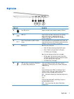
Страница 15: ... Off The battery is not charging When AC power is disconnected battery not charging Blinking amber The battery has reached a low battery level When the battery has reached a critical battery level the battery light begins blinking rapidly Off The battery is not charging 5 USB Type C power connector and Thunderbolt port with HP Sleep and Charge 2 Connect an AC adapter that has a USB Type C connecto...

Страница 16: ...mera activity tracker or smartwatch 4 Audio out headphone Audio in microphone combo jack Connects optional powered stereo speakers headphones earbuds a headset or a television audio cable Also connects an optional headset microphone This jack does not support optional standalone microphones WARNING To reduce the risk of personal injury adjust the volume before putting on headphones earbuds or a he...

Страница 17: ...talled on your product 5 WLAN antennas Send and receive wireless signals to communicate with wireless local area networks WLANs The antennas are not visible from the outside of the computer For optimal transmission keep the areas immediately around the antennas free from obstructions For wireless regulatory notices see the section of the Regulatory Safety and Environmental Notices that applies to ...

Страница 18: ...ons like the right button on an external mouse The antenna is not visible from the outside of the computer For optimal transmission keep the area immediately around the antenna free from obstructions For wireless regulatory notices see the section of the Regulatory Safety and Environmental Notices that applies to your country or region To access this guide 1 Type support in the taskbar search box ...

Страница 19: ...Privacy screen is on which helps prevent side angle viewing 4 Fn lock light On The fn key is locked For more information see Hot keys select products only on page 16 5 Mute light On Computer sound is off Off Computer sound is on 6 Microphone mute light On Microphone is off Off Microphone is on 7 Num lk light On Num lock is on 8 Wireless light On An integrated wireless device such as a wireless loc...

Страница 20: ... the computer is off press the button to turn on the computer When the computer is on press the button briefly to initiate Sleep When the computer is in the Sleep state press the button briefly to exit Sleep When the computer is in Hibernation press the button briefly to exit Hibernation CAUTION Pressing and holding down the power button results in the loss of unsaved information 12 Chapter 2 Exte...

Страница 21: ...utton for at least 5 seconds to turn off the computer To learn more about your power settings see your power options Right click the Power meter icon and then select Power Options 2 Speakers Produce sound 3 Fingerprint reader select products only Allows a fingerprint logon to Windows instead of a password logon Keyboard area 13 ...

Страница 22: ...ns See Action keys on page 15 5 Embedded numeric keypad A numeric keypad superimposed over the keyboard alphabet keys When fn num lk is pressed the keypad can be used like an external numeric keypad Each key on the keypad performs the function indicated by the icon in the upper right corner of the key NOTE If the keypad function is active when the computer is turned off that function is reinstated...

Страница 23: ...e privacy screen NOTE To quickly turn on the highest privacy setting press fn p Decreases the screen brightness incrementally as long as you hold down the key Increases the screen brightness incrementally as long as you hold down the key Mutes or restores speaker sound Decreases speaker volume incrementally while you hold down the key Increases speaker volume incrementally while you hold down the ...

Страница 24: ... The action key feature is enabled at the factory You can disable this feature by pressing and holding the fn key and the shift key The fn lock light will turn on After you have disabled the action key feature you can still perform each function by pressing the fn key in combination with the appropriate action key Hot keys select products only A hot key is the combination of the fn key and another...

Страница 25: ...irflow to cool internal components NOTE The computer fan starts up automatically to cool internal components and prevent overheating It is normal for the internal fan to cycle on and off during routine operation 2 Speakers Produce sound Bottom 17 ...

Страница 26: ...r the internal fan to cycle on and off during routine operation Locating system information Important system information is located on the bottom edge of the tablet or on the keyboard base You may need the information when travelling internationally or when you contact support 1 Serial number 2 Product number 3 Model number 4 Warranty period 18 Chapter 2 External component identification ...

Страница 27: ...e fn esc key combination to display the System Information screen which provides the product name and serial number of your computer as well as information about the memory processor BIOS and keyboard Locating system information 19 ...

Страница 28: ... for your computer go to http partsurfer hp com select your country or region and then follow the on screen instructions NOTE Details about your computer including model serial number product key and length of warranty are on the service tag at the bottom of your computer See Locating system information on page 18 for details 20 Chapter 3 Illustrated parts catalog ...

Страница 29: ...Item Component Spare part number 1 Display panel see Display assembly on page 48 Computer major components 21 ...

Страница 30: ... D61 For use in Israel L02267 BB1 For use in Italy L02267 061 For use in Japan L02267 291 For use in Latin America L02267 161 For use in the Netherlands L02267 B31 For use in Northwest Africa L02267 FP1 For use in Norway L02267 091 For use in Portugal L02267 131 For use in Romania L02267 271 For use in Russia L02267 251 For use in Saudi Arabia L02267 161 For use in Slovenia L02267 BA1 For use in S...

Страница 31: ...use in Hungary L02268 211 For use in Iceland L02268 DD1 For use in India L02268 D61 For use in Israel L02268 BB1 For use in Italy L02268 061 For use in Japan L02268 291 For use in Latin America L02268 161 For use in the Netherlands L02268 B31 For use in Northwest Africa L02268 FP1 For use in Norway L02268 091 For use in Portugal L02268 131 For use in Romania L02268 271 For use in Russia L02268 251...

Страница 32: ...System board on page 41 12 Speaker kit L02246 001 13 Rear speakers 14 Thermal vent L02241 001 15 Base enclosure L02251 001 Miscellaneous parts Component Spare part number 65W Adapter nPFC RC USB C 3 pin 860209 850 90W Adapter PFC USB C 3 pin 904144 850 90W PFC Adapter S 3P 4 5 mm 710413 001 Bracket kit L02248 001 Cable kit L02259 001 Dummy SIM card L02250 001 Essential Top Load Case 679921 001 Hea...

Страница 33: ...0 001 HP USB C to VGA Adapter 831751 001 HP USB C to DisplayPort Adapter 831753 001 HP USB C to RJ45 Adapter 855560 001 Miscellaneous kit L02252 001 Plastics kit L02245 001 Power cord AC power cord C5 DOM black 213349 001 AC line C5 NEMA 1 00m 213349 009 213349 015 For use in Europe 213350 001 213350 009 213350 014 For use in the United Kingdom and Singapore 213351 001 213351 008 213351 013 For us...

Страница 34: ...2 For use in South Africa 361240 007 For use in Taiwan 393313 001 393313 003 393313 007 For use in Israel 398063 001 398063 003 398063 008 For use in Argentina 401300 001 401300 007 401300 011 For use in India 404827 001 404827 003 404827 008 For use in Brazil 438722 001 438722 004 438722 008 Duck head For use in the United States 854702 001 For use in Europe and South Korea 854703 001 For use in ...

Страница 35: ...Component Spare part number For use in India 914726 001 Screw kit L02258 001 Miscellaneous parts 27 ...

Страница 36: ...he following sections include some of the considerations that you must keep in mind during disassembly and assembly procedures NOTE As you remove each subassembly from the computer place the subassembly and all accompanying screws away from the work area to prevent damage Plastic parts CAUTION Using excessive force during disassembly and reassembly can damage plastic parts Use care when handling t...

Страница 37: ...utions Before removing or inserting a hard drive shut down the computer If you are unsure whether the computer is off or in Hibernation turn the computer on and then shut it down through the operating system Before handling a drive be sure that you are discharged of static electricity While handling a drive avoid touching the connector Before removing an optical drive be sure that a disc is not in...

Страница 38: ...components in their electrostatic safe containers until you are ready to install them Before touching an electronic component discharge static electricity by using the guidelines described in this section Avoid touching pins leads and circuitry Handle electronic components as little as possible If you remove a component place it in an electrostatic safe container The following table shows how humi...

Страница 39: ...to ground and that proper materials are selected to avoid static charging When grounding is not possible use an ionizer to dissipate electric charges Workstation guidelines Follow these grounding workstation guidelines Cover the workstation with approved static shielding material Use a wrist strap connected to a properly grounded work surface and use properly grounded tools and equipment Use condu...

Страница 40: ...tor and ground To be effective the conductive equipment must be worn in contact with the skin The following grounding equipment is recommended to prevent electrostatic damage Antistatic tape Antistatic smocks aprons and sleeve protectors Conductive bins and other assembly or soldering aids Nonconductive foam Conductive tabletop workstations with ground cords of one megohm resistance Static dissipa...

Страница 41: ...acement procedures NOTE Details about your computer including model serial number product key and length of warranty are on the service tag at the bottom of your computer See Locating system information on page 18 for details NOTE HP continually improves and changes product parts For complete and current information on supported parts for your computer go to http partsurfer hp com select your coun...

Страница 42: ... computer 2 Disconnect all external devices connected to the computer 3 Disconnect the power from the computer by first unplugging the power cord from the AC outlet and then unplugging the AC adapter from the computer Remove the base enclosure Remove 8 T8 screws and then lift the base enclosure to remove it Reverse this procedure to install the base enclosure 34 Chapter 5 Removal and replacement p...

Страница 43: ...onnect all external devices connected to the computer 3 Disconnect the power from the computer by first unplugging the power cord from the AC outlet and then unplugging the AC adapter from the computer 4 Remove the base enclosure see Base enclosure on page 34 Remove the battery 1 Disconnect the battery cable from the system board 1 2 Remove 6 M2 0x4 screws 2 and then lift the battery to remove it ...

Страница 44: ...he power from the computer by first unplugging the power cord from the AC outlet and then unplugging the AC adapter from the computer 4 Remove the base enclosure see Base enclosure on page 34 and then remove the following components Battery see Battery on page 35 Remove the front speakers 1 Disconnect the speaker cable 1 2 Remove 4 M2 0 x L6 2 5 2 0 8 screws 2 3 Release the speaker cable from the ...

Страница 45: ...Reverse this procedure to install the front speakers Component replacement procedures 37 ...

Страница 46: ...ter 2 Disconnect all external devices connected to the computer 3 Disconnect the power from the computer by first unplugging the power cord from the AC outlet and then unplugging the AC adapter from the computer 4 Remove the base enclosure see Base enclosure on page 34 and then remove the following components a Battery see Battery on page 35 b Front speakers see Front speakers on page 36 Remove th...

Страница 47: ...2 Remove 1 M2 I screw 2 and then remove the WWAN module from the connector 3 Reverse this procedure to install the WWAN module Component replacement procedures 39 ...

Страница 48: ...ct all external devices connected to the computer 3 Disconnect the power from the computer by first unplugging the power cord from the AC outlet and then unplugging the AC adapter from the computer 4 Remove the base enclosure see Base enclosure on page 34 and then remove the following components a Battery see Battery on page 35 b Front speakers see Front speakers on page 36 c WWAN module see WWAN ...

Страница 49: ...emory UMA graphics and the Windows operating system L02235 601 i7 7600U processor with 16 GB and UMA graphics L02236 001 i7 7600U processor with 16 GB memory UMA graphics and the Windows operating system L02236 601 i7 7600U processor with 8 GB and UMA graphics L02237 001 i7 7600U processor with 8 GB memory UMA graphics and the Windows operating system L02237 601 IMPORTANT Make special note of each...

Страница 50: ...oard xi Front speakers Remove the system board NOTE The U series system board thermal solution has only a left side fan and a dummy fan on the right side 1 Remove 5 M2 0 4 screws from the system board 42 Chapter 5 Removal and replacement procedures for authorized service provider parts ...

Страница 51: ... of the system board 1 disconnect the battery cable 2 disconnect the rear speaker cable 3 and then lift the system board to remove it 4 Reverse this procedure to install the system board Component replacement procedures 43 ...

Страница 52: ...om the computer by first unplugging the power cord from the AC outlet and then unplugging the AC adapter from the computer 4 Remove the base enclosure see Base enclosure on page 34 and then remove the following components Battery see Battery on page 35 Remove the fingerprint reader 1 Remove 1 M2 2 I screw 1 and then lift the fingerprint reader cover to remove it 2 2 Lift the fingerprint reader to ...

Страница 53: ...the computer 3 Disconnect the power from the computer by first unplugging the power cord from the AC outlet and then unplugging the AC adapter from the computer 4 Remove the base enclosure see Base enclosure on page 34 and then remove the following components Battery see Battery on page 35 Remove the NFC module 1 Disconnect the NFC cable 1 and then disconnect the NFC module from the TouchPad 2 2 L...

Страница 54: ... the computer by first unplugging the power cord from the AC outlet and then unplugging the AC adapter from the computer 4 Remove the base enclosure see Base enclosure on page 34 and then remove the following components Battery see Battery on page 35 Remove the TouchPad 1 Disconnect the NFC cable 1 and the TouchPad cable 2 2 Remove 5 M2 2 I screws 3 and then lift the TouchPad to remove it 4 Revers...

Страница 55: ...onnected to the computer 3 Disconnect the power from the computer by first unplugging the power cord from the AC outlet and then unplugging the AC adapter from the computer 4 Remove the base enclosure see Base enclosure on page 34 and then remove the following components Battery see Battery on page 35 Remove the RTC battery Disconnect the RTC battery cable and then lift the battery to remove it Re...

Страница 56: ... 001 IMPORTANT Make special note of each screw and screw lock size and location during removal and replacement Before removing the display assembly follow these steps 1 Shut down the computer 2 Disconnect all external devices connected to the computer 3 Disconnect the power from the computer by first unplugging the power cord from the AC outlet and then unplugging the AC adapter from the computer ...

Страница 57: ...Reverse this procedure to install the display assembly Component replacement procedures 49 ...

Страница 58: ...t unplugging the power cord from the AC outlet and then unplugging the AC adapter from the computer 4 Remove the base enclosure see Base enclosure on page 34 and then remove the following components a Battery see Battery on page 35 b System board see System board on page 41 c Display assembly see Display assembly on page 48 Remove the thermal vent Remove 4 M2 5 4 5 screws 1 and then lift the therm...

Страница 59: ...ter 3 Disconnect the power from the computer by first unplugging the power cord from the AC outlet and then unplugging the AC adapter from the computer 4 Remove the base enclosure see Base enclosure on page 34 and then remove the following components a Battery see Battery on page 35 b System board see System board on page 41 Remove the power button board Remove 2 M2 2 I screws 1 lift the power but...

Страница 60: ...SB port but you must first disable FastBoot 1 Turn on or restart the computer and when the HP logo appears press f9 to enter the Boot Device Options menu 2 Clear the check box for Fast Boot 3 To save your changes and exit select the Save icon in the lower right corner of the screen and then follow the on screen instructions or Select Main select Save Changes and Exit and then press enter Your chan...

Страница 61: ...lect products the selections may display Restore Defaults instead of Apply Factory Defaults and Exit 3 Follow the on screen instructions 4 To save your changes and exit select the Save icon in the lower right corner of the screen and then follow the on screen instructions or Select Main select Save Changes and Exit and then press enter Your changes go into effect when the computer restarts NOTE Yo...

Страница 62: ... select Check for updates and messages 3 Follow the on screen instructions 4 At the download area follow these steps a Identify the most recent BIOS update and compare it to the BIOS version currently installed on your computer Make a note of the date name or other identifier You may need this information to locate the update later after it has been downloaded to your hard drive b Follow the on sc...

Страница 63: ...ly HP will not be responsible for any related liabilities TPM provides additional security for your computer You can modify the TPM settings in Computer Setup BIOS NOTE If you change the TPM setting to Hidden TPM is not visible in the operating system To access TPM settings in Computer Setup 1 Start Computer Setup See Starting Computer Setup on page 52 2 Select Security select TPM Embedded Securit...

Страница 64: ...ow to correct the problem NOTE To start diagnostics on a convertible computer your computer must be in notebook mode and you must use the keyboard attached To start HP PC Hardware Diagnostics UEFI follow these steps 1 Turn on or restart the computer and quickly press esc 2 Press f2 The BIOS searches three places for the diagnostic tools in the following order a Connected USB drive NOTE To download...

Страница 65: ...s UEFI to your computer It executes the diagnostics on your computer and then may upload results to a preconfigured server Using the Remote HP PC Hardware Diagnostics setting in Computer Setup BIOS you can perform the following customizations Set a schedule for running diagnostics unattended You can also start diagnostics immediately in interactive mode by selecting Execute Remote HP PC Hardware D...

Страница 66: ...Diagnostics UEFI to configure a server for remote diagnostics or to customize which diagnostic tests are run go to http www hp com support Select Find your product and then follow the on screen instructions 58 Chapter 7 Using HP PC Hardware Diagnostics UEFI ...

Страница 67: ... operating system in cases where the hard drive is corrupted or has been replaced For information on creating recovery media see Creating HP Recovery media select products only on page 59 For information on the recovery options that are available using the recovery media see Using Windows tools on page 60 Use Windows tools to create system restore points and create backups of personal information ...

Страница 68: ...e an external optical drive purchased separately to create recovery discs If you use an external optical drive it must be connected directly to a USB port on the computer the drive cannot be connected to a USB port on an external device such as a USB hub If you cannot create DVD media yourself you can obtain recovery discs for your computer from HP You can find contact information on the HP websit...

Страница 69: ...n page 59 On select products if you want to recover the computer s original factory partition and content or if you have replaced the hard drive you can use the Factory Reset option of HP Recovery media For more information see Recovering using HP Recovery Manager on page 61 On select products if you want to remove the Recovery partition to reclaim hard drive space HP Recovery Manager offers the R...

Страница 70: ...ed at the factory The HP Recovery partition select products only allows System Recovery only Using the HP Recovery partition select products only The HP Recovery partition allows you to perform a system recovery without the need for recovery discs or a recovery USB flash drive This type of recovery can be used only if the hard drive is still working To start HP Recovery Manager from the HP Recover...

Страница 71: ...ot options For tablets without keyboards Turn on or restart the tablet and then quickly hold down the volume up button then select f9 or Turn on or restart the tablet and then quickly hold down the volume down button then select f9 3 Select the optical drive or USB flash drive from which you want to boot 4 Follow the on screen instructions Removing the HP Recovery partition select products only HP...

Страница 72: ...W USB C 5 V dc 3 A 9 V dc 3 A 10 V dc 5 A 12 V dc 5 A 15 V dc 5 A 20 V dc 4 5 A 90 W USB C Temperature Operating 5 C to 35 C 41 F to 95 F Nonoperating 20 C to 60 C 4 F to 140 F Relative humidity noncondensing Operating 10 to 90 Nonoperating 5 to 95 Maximum altitude unpressurized Operating 15 m to 3 048 m 50 ft to 10 000 ft Nonoperating 15 m to 12 192 m 50 ft to 40 000 ft NOTE Applicable product sa...

Страница 73: ...ts Format RGB Configuration 1920 x 1080 FHD PPI 157 Viewing Angle UWVA 85 85 85 85 14 inch LCD FHD 1920x1080 Anti Glare WLED UWVA 72percent cg 700nits eDP 1 3 PSR ultraslim Privacy Metric U S Active Area W x H 300 56 x 187 57 max x2 2 max mm 12 18 x 6 85 in Dimensions W x H 293 76 x 165 24 mm 12 634 x 8 094 in Diagonal 35 56 cm 13 3 in Weight 160 g max Interface eDP 1 3 w PSR Surface Treatment BV ...

Страница 74: ... Dimensions W x H 293 76 x 165 24 mm 12 634 x 8 094 in Diagonal 35 56 cm 13 3 in Thickness 3 0 mm max Weight 290 g max Interface eDP 1 3 w PSR Surface Treatment BV Contrast Ratio 800 1 typical Refresh Rate 60 Hz Brightness 400 nits PPI 315 Format RGB Backlight LED Configuration 3840 x 2160 UHD Viewing angle UWVA 85 85 85 85 Touch Enabled Yes 66 Chapter 9 Specifications ...

Страница 75: ... to hard drive storage capacity Actual accessible capacity is less NOTE Certain restrictions and exclusions apply Contact technical support for details 2280 M2 SATA 3 Self Encrypted OPAL2 TLC 256 GB Dimensions Height 0 09 in 2 3 mm Width 0 87 in 22 mm Weight 0 02 lb 10 g Interface type ATA 8 SATA 3 0 Transfer rate Maximum Sequential Read Up to 530 MB s Maximum Sequential Write Up to 515 MB s Logic...

Страница 76: ... TRIM L1 2 TRIM L1 2 TRIM L1 2 1 GB 1 billion bytes when referring to hard drive storage capacity Actual accessible capacity is less NOTE Certain restrictions and exclusions apply Contact technical support for details 2280 M2 PCIe 3x4 SS NVMe 512 GB Dimensions Height 0 09 in 2 3 mm Width 0 87 in 22 mm Weight 0 02 lb 10 g Interface type PCIe NVMe Gen3X4 Transfer rate Maximum Sequential Read Up to 3...

Страница 77: ...equirements are applicable to all countries and regions The length of the power cord set must be at least 1 0 m 3 3 ft and no more than 2 0 m 6 5 ft All power cord sets must be approved by an acceptable accredited agency responsible for evaluation in the country or region where the power cord set will be used The power cord sets must have a minimum current capacity of 10 A and a nominal voltage ra...

Страница 78: ...orea KTL 5 Sweden SEMKO 1 Switzerland SEV 1 Taiwan BSMI 6 Thailand TISI 1 The United Kingdom ASTA 1 The United States UL 2 1 The flexible cord must be Type HO5VV F 3 conductor 0 75 mm conductor size Power cord set fittings appliance coupler and wall plug must bear the certification mark of the agency responsible for evaluation in the country or region where it will be used 2 The flexible cord must...

Страница 79: ...e CCC certification mark 5 The flexible cord must be Type H05VV F 3 conductor 0 75 mm conductor size KTL logo and individual approval number must be on each element Corset approval number and logo must be printed on a flag label 6 The flexible cord must be Type HVCTF 3 conductor 1 25 mm conductor size Power cord set fittings appliance coupler cable and wall plug must bear the BSMI certification ma...

Страница 80: ...low to restore the nonvolatile memory that can contain personal data Restoring or reprogramming nonvolatile memory that does not store personal data is neither necessary nor recommended a Turn on or restart the computer and then quickly press esc NOTE If the system has a BIOS administrator password enter the password at the prompt b Select Main select Apply Factory Defaults and Exit and then selec...

Страница 81: ...rase data from an SSD or Clear the contents of the drive by using the following BIOS Setup Secure Erase command option steps IMPORTANT If you clear data using Secure Erase it cannot be recovered a Turn on or restart the computer and then quickly press esc b Select the Security menu and scroll down to the Utilities menu c Select Hard Drive Utilities d Under Utilities select Secure Erase select the ...

Страница 82: ...4 KBytes not customer accessible No Yes Stores NIC configuration and NIC firmware NIC EEPROM is programmed using a utility from the NIC vendor that can be run from DOS A utility is required to write data to this memory and is available from the NIC vendor Writing data to this ROM in an inappropriate manner will render the NIC non functional DIMM Serial Presence Detect SPD configuration data 256 By...

Страница 83: ...pplied using this utility Bluetooth flash select products only 2 Mbit No Yes Stores Bluetooth configuration and firmware Bluetooth flash is programmed at the factory Tools for writing data to this memory are not publicly available but can be obtained from the silicon vendor A utility is required for writing data to this memory and is made available through newer versions of the driver whenever the...

Страница 84: ...ality beyond that of the legacy BIOS In addition the UEFI BIOS works to initialize the computer s hardware before loading and executing the OS the run time environment allows the loading and execution of software programs from storage devices to provide more functionality such as advanced hardware diagnostics with the ability to display more detailed system information and advanced firmware manage...

Страница 85: ...oot Keys a Turn on or restart the computer and then quickly press esc b Select the Security menu select Secure Boot Configuration and then follow the on screen instructions c At the Secure Boot Configuration window select Secure Boot select Clear Secure Boot Keys and then follow the on screen instructions to continue Using HP Sure Start select models only Select computer models are configured with...

Страница 86: ...in general household waste Follow the local laws and regulations in your area for battery disposal HP encourages customers to recycle used electronic hardware HP original print cartridges and rechargeable batteries For more information about recycling programs see the HP Web site at http www hp com recycle 78 Chapter 12 Recycling ...

Страница 87: ...art Computer Setup 52 computer setup 52 computer specifications 64 configurable software product description 5 connector power 7 D display removal 48 specifications 65 display panel product description 1 dock spare part numbers 25 docking product description 3 docking station spare part numbers 25 duck head spare part number 26 dummy SIM card spare part numbers 24 DVDRW spare part numbers 25 E emb...

Страница 88: ...it spare part number 25 pointing device product description 3 ports HDMI 7 product description 3 USB 3 x SuperSpeed port with HP Sleep and Charge 7 8 USB Type C power connector and Thunderbolt port with HP Sleep and Charge 7 power button identifying 12 power connector identifying 7 power cord requirements for all countries 69 requirements for specific countries and regions 70 set requirements 69 p...

Страница 89: ...personal data from volatile 72 system recovery 61 system restore point creating 60 system restore point creating 59 T thermal vent removal 50 spare part number 24 Thunderbolt port with HP Sleep and Charge identifying USB Type C 7 TouchPad buttons 10 removal 46 spare part number 24 TouchPad zone identifying 10 TPM settings 55 U USB 3 x SuperSpeed port with HP Sleep and Charge identifying 7 8 USB to...

Отзывы: