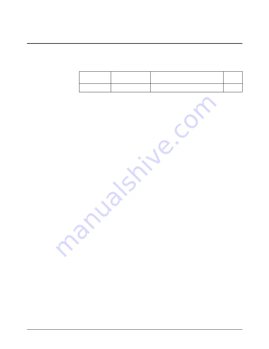
CALibration:VALue:RESistance
CALibration:VALue:RESistance <
value
>
enters a new measured value to be used
as the internal calibration resistor constant by the module.
Parameters
Parameter
Name
Parameter
Type
Range of
Values
Default
<
value
>
numeric (float 32)
Must be > 0 ohms
none
Comments
•
The new calibration constant is used by the module but not stored in non-volatile
memory.
•
This command is used together with the
CALibration:CONFigure:RESistance?
query to calibrate the internal current calibration resistor.
•
The internal calibration resistor should be calibrated before calibrating channels in
current mode. When calibrating at the CAL connections and using the internal
calibration resistor, the value need only be entered once to calibrate all channels.
•
If using an external resistor to calibrate current mode, you must calibrate at each
channel output. External resistances in the range of 50
Ω
to 500
Ω
are recommended.
•
Refer to Appendix D, “Voltage/Current Output Adjustment”, starting on page 157,
for additional information about this command.
•
Related Commands:
CALibration:STORe
,
CALibration:CONFigure:RESistance?
CALibration
69 HP E1418A SCPI Command Reference
Chapter 3
Содержание E1418A
Страница 6: ...Notes 6 Contents HP E1418A 8 16 Channel D A Converter Module ...
Страница 10: ...Notes 10 HP E1418A User s Manual ...
Страница 12: ...12 HP E1418A User s Manual ...
Страница 105: ...TRIGger 105 HP E1418A SCPI Command Reference Chapter 3 ...
Страница 111: ...Notes HP E1418A Command Quick Reference 111 HP E1418A SCPI Command Reference Chapter 3 ...
Страница 135: ...135 HP E1418A Register Based Programming Appendix B ...
Страница 157: ...Notes 156 HP E1418A Error Messages Appendix C ...
Страница 164: ...Figure D 4 Resistance Calibration Connections CAL Appendix D Voltage Current Output Adjustment 163 ...
Страница 170: ...Notes Appendix D Voltage Current Output Adjustment 169 ...
Страница 174: ...Figure E 1 8 Channel Disassembly 172 Configuration and Disassembly Appendix E ...
Страница 175: ...Figure E 2 16 Channel Disassembly Appendix E Configuration and Disassembly 173 ...
Страница 177: ...Figure E 3 Plug on Channel Locations Figure E 4 Installing Plug on Modules Appendix E Configuration and Disassembly 175 ...
Страница 192: ...Notes 192 HP E1418A 8 16 Channel D A Converter Module Index ...

