Using *OPC?
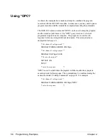
As shown, the examples have made no attempt to coordinate the program
execution with the HP E1418A module. In some cases, you may need to pause
program execution until the module has completed executing the commands.
The IEEE-488 common command
*OPC?
can be used to keep the program
and the module synchronized. The
*OPC?
query returns a 1 when all
programmed operations are complete. The program can wait for the
response before executing additional statements. The returned value is
unimportant (always a 1).
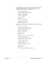
/* Set channel 1 voltage mode */
SOURce1:FUNCtion:MODE VOLTage
/* Set channel 1 voltage output */
SOURce1:VOLTage 5.000
/* Turn on the output */
OUTPut1 ON
*OPC?
/* enter the response */
*OPC?
is used to synchronize the program with the module since program
execution waits for the response. The command may be combined using the
;
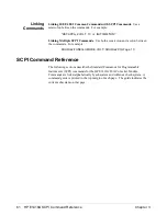
as described under “Linking Commands” on page 61. For example,
/* Set channel 1 voltage mode */
SOURce1:FUNCtion:MODE VOLTage;*OPC?
/* enter the response */
56 Programming Examples
Chapter 2
Содержание E1418A
Страница 6: ...Notes 6 Contents HP E1418A 8 16 Channel D A Converter Module ...
Страница 10: ...Notes 10 HP E1418A User s Manual ...
Страница 12: ...12 HP E1418A User s Manual ...
Страница 105: ...TRIGger 105 HP E1418A SCPI Command Reference Chapter 3 ...
Страница 111: ...Notes HP E1418A Command Quick Reference 111 HP E1418A SCPI Command Reference Chapter 3 ...
Страница 135: ...135 HP E1418A Register Based Programming Appendix B ...
Страница 157: ...Notes 156 HP E1418A Error Messages Appendix C ...
Страница 164: ...Figure D 4 Resistance Calibration Connections CAL Appendix D Voltage Current Output Adjustment 163 ...
Страница 170: ...Notes Appendix D Voltage Current Output Adjustment 169 ...
Страница 174: ...Figure E 1 8 Channel Disassembly 172 Configuration and Disassembly Appendix E ...
Страница 175: ...Figure E 2 16 Channel Disassembly Appendix E Configuration and Disassembly 173 ...
Страница 177: ...Figure E 3 Plug on Channel Locations Figure E 4 Installing Plug on Modules Appendix E Configuration and Disassembly 175 ...
Страница 192: ...Notes 192 HP E1418A 8 16 Channel D A Converter Module Index ...


