


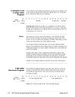


Module Serial
Number Registers
The Module Serial Number Registers provides a 10-byte module serial
number stored in non-volatile memory.
Address
Base + 18E
16
Bit
15
14
13
12
11
10
09
08
07
06
05
04
03
02
01
00
READ
2nd Least Significant Byte
Least Significant Byte
Address
Base + 190
16
Bit
15
14
13
12
11
10
09
08
07
06
05
04
03
02
01
00
READ
4th Least Significant Byte
3 rd Least Significant Byte
Address
Base + 192
16
Bit
15
14
13
12
11
10
09
08
07
06
05
04
03
02
01
00
READ
6th Least Significant Byte
5th Least Significant Byte
Address
Base + 194
16
Bit
15
14
13
12
11
10
09
08
07
06
05
04
03
02
01
00
READ
8th Least Significant Byte
7th Least Significant Byte
Address
Base + 196
16
Bit
15
14
13
12
11
10
09
08
07
06
05
04
03
02
01
00
READ
Most Significant Byte
9th Least Significant Byte
Register Example
This example demonstrates using direct register access to set a calibrated
voltage output. The example is in HP BASIC and uses a command module
controlled via HP-IB.
•
•
•
679
Reg_offset(0) = 0
! ID / Logical Address Register.
680
Reg_offset(1) = 2
! Device Type Register.
681
Reg_offset(2) = 4
! Status/Control Register.
682
Reg_offset(3) = 6
! VXI Offset Register.
683
Reg_offset(4) = 8
! Calibration Control Register.
684
Reg_offset(5) = 10
! Card Configuration Register.
685
Reg_offset(6) = 12
! Software Trigger Register.
686
Reg_offset(7) = 14
! Trigger Control Register.
687
Reg_offset(8) = 16
! Interrupt Control Register.
688
Reg_offset(9) = 18
! Interrupt Status Register.
689
Reg_offset(10) = 20
! Isolation Status Register.
690
Reg_offset(11) = 22
! Program Jumper Register.
691
Reg_offset(12) = 24
! Channel Trigger Register.
692
Reg_offset(13) = 26
! Channel Mode Register.
693
Reg_offset(14) = 28
! Relay Control Register.
694
Reg_offset(15) = 30
! Card Control A24 Window Register.
695
Reg_offset(16) = 32
! A_24 Window Register (Channel 1 DAC and CAL).
696
Reg_offset(17) = 34
! A_24 Window Register (Channel 2 DAC and CAL).
Appendix B
HP E1418A Register-Based Programming 152
Содержание E1418A
Страница 6: ...Notes 6 Contents HP E1418A 8 16 Channel D A Converter Module ...
Страница 10: ...Notes 10 HP E1418A User s Manual ...
Страница 12: ...12 HP E1418A User s Manual ...
Страница 105: ...TRIGger 105 HP E1418A SCPI Command Reference Chapter 3 ...
Страница 111: ...Notes HP E1418A Command Quick Reference 111 HP E1418A SCPI Command Reference Chapter 3 ...
Страница 135: ...135 HP E1418A Register Based Programming Appendix B ...
Страница 157: ...Notes 156 HP E1418A Error Messages Appendix C ...
Страница 164: ...Figure D 4 Resistance Calibration Connections CAL Appendix D Voltage Current Output Adjustment 163 ...
Страница 170: ...Notes Appendix D Voltage Current Output Adjustment 169 ...
Страница 174: ...Figure E 1 8 Channel Disassembly 172 Configuration and Disassembly Appendix E ...
Страница 175: ...Figure E 2 16 Channel Disassembly Appendix E Configuration and Disassembly 173 ...
Страница 177: ...Figure E 3 Plug on Channel Locations Figure E 4 Installing Plug on Modules Appendix E Configuration and Disassembly 175 ...
Страница 192: ...Notes 192 HP E1418A 8 16 Channel D A Converter Module Index ...


