


Calibration
Resistor Value
Registers
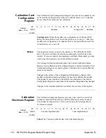
The Calibration Resistor Value Registers store the value of the resistor used
to calibrate current output. The Calibration resistor value is a 32-bit value
and requires two 16-bit registers. These registers are non-volatile.
Address
Base + 180
16
Bit
15
14
13
12
11
10
09
08
07
06
05
04
03
02
01
00
READ
2nd Least Significant Byte
Least Significant Byte
WRITE
Address
Base + 182
16
Bit
15
14
13
12
11
10
09
08
07
06
05
04
03
02
01
00
READ
Most Significant Byte
2nd Most Significant Byte
WRITE
Value: The 32-bit resistor value (in ohms) is written to two adjacent 16-bit
registers. The value is a float 32 format.
Voltage Calibration
Status Register
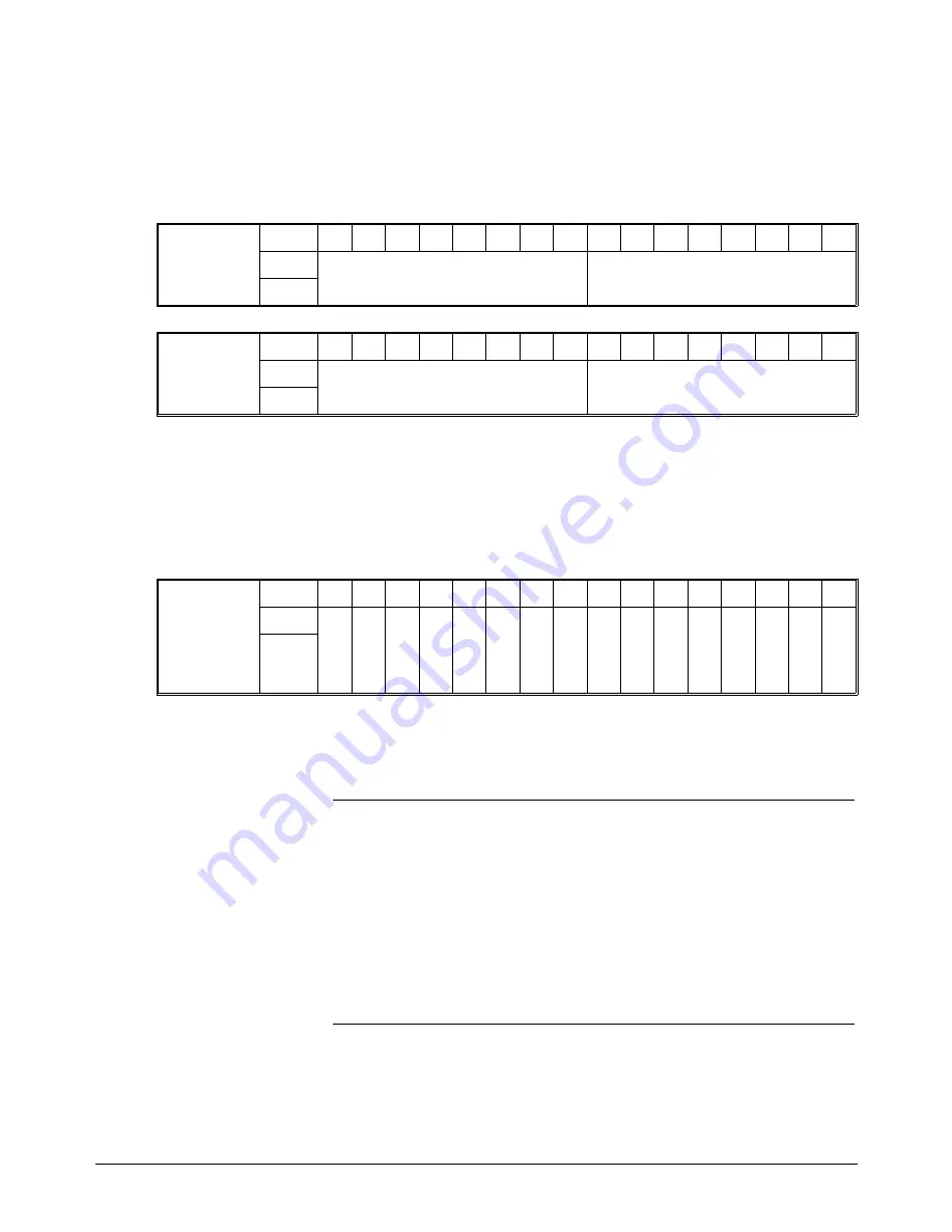
The Voltage Calibration Status Register provides a non-volatile record of
the voltage calibration status for each channel. This register is non-volatile.
Address
Base + 184
16
Bit
15
14
13
12
11
10
09
08
07
06
05
04
03
02
01
00
READ
Ch
16
Volt
Cal
Stat
Ch
15
Volt
Cal
Stat
Ch
14
Volt
Cal
Stat
Ch
13
Volt
Cal
Stat
Ch
12
Volt
Cal
Stat
Ch
11
Volt
Cal
Stat
Ch
10
Volt
Cal
Stat
Ch
09
Volt
Cal
Stat
Ch
08
Volt
Cal
Stat
Ch
07
Volt
Cal
Stat
Ch
06
Volt
Cal
Stat
Ch
05
Volt
Cal
Stat
Ch
04
Volt
Cal
Stat
Ch
03
Volt
Cal
Stat
Ch
02
Volt
Cal
Stat
Ch
01
Volt
Cal
Stat
WRITE
Ch XX Cal Stat: This field is set to a one (1) when the channel has been
successfully voltage calibrated. This field is set to a zero (0) when the
channel is not voltage calibrated.
Notes
This register is not set or used by the hardware. The HP E1418A SCPI
driver, if used to calibrate the module, automatically sets the bits in this
register. If you use register programming to calibrate this module, you may
wish to use this register to record the calibration status.
The Voltage Calibration Status Register, the Current Calibration Status
Register, the Calibration Isolation Status Register, and the Calibration Card
Configuration Register are used together to store the overall calibration
status of the module.
Appendix B
HP E1418A Register-Based Programming 148
Содержание E1418A
Страница 6: ...Notes 6 Contents HP E1418A 8 16 Channel D A Converter Module ...
Страница 10: ...Notes 10 HP E1418A User s Manual ...
Страница 12: ...12 HP E1418A User s Manual ...
Страница 105: ...TRIGger 105 HP E1418A SCPI Command Reference Chapter 3 ...
Страница 111: ...Notes HP E1418A Command Quick Reference 111 HP E1418A SCPI Command Reference Chapter 3 ...
Страница 135: ...135 HP E1418A Register Based Programming Appendix B ...
Страница 157: ...Notes 156 HP E1418A Error Messages Appendix C ...
Страница 164: ...Figure D 4 Resistance Calibration Connections CAL Appendix D Voltage Current Output Adjustment 163 ...
Страница 170: ...Notes Appendix D Voltage Current Output Adjustment 169 ...
Страница 174: ...Figure E 1 8 Channel Disassembly 172 Configuration and Disassembly Appendix E ...
Страница 175: ...Figure E 2 16 Channel Disassembly Appendix E Configuration and Disassembly 173 ...
Страница 177: ...Figure E 3 Plug on Channel Locations Figure E 4 Installing Plug on Modules Appendix E Configuration and Disassembly 175 ...
Страница 192: ...Notes 192 HP E1418A 8 16 Channel D A Converter Module Index ...


