


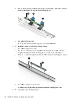


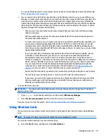


2.
Remove the three Phillips PM2.5×4.1 screws (1) that secure the power connector cable bracket to
the keyboard/top cover.
3.
Remove the power connector cable bracket (2).
4.
Remove the Phillips PM2.0×3.2 screw (3) that secures the battery spacer to the keyboard/top cover.
5.
Remove the battery spacer (4).
The battery spacer is included in the Plastics Kit, spare part number 909633-001.
6.
Remove the two Phillips PM2.0×3.2 screws (5) that secure the system board spacer to the keyboard/
top cover.
7.
Remove the system board spacer (6).
The system board spacer is available in the Plastics Kit, spare part number 909633-001.
8.
Remove the two Phillips PM2.5×4.1 screws (7) that secure the USB bracket to the keyboard/top cover.
9.
Remove the USB bracket (8).
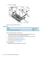
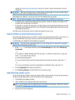
10.
Remove the two Phillips PM2.0×3.2 screws (1) that secure the system board to the keyboard/top cover.
Component replacement procedures
49
Содержание CTO 13t-ab000
Страница 4: ...iv Safety warning notice ...
Страница 7: ...11 Recycling 66 Index 67 vii ...
Страница 8: ...viii ...
Страница 23: ...Computer major components Computer major components 15 ...


