background image

Processor

1.

Prepare the computer for disassembly (

Preparation for Disassembly on page 27

).

2.

Remove the computer access panel (

Computer Access Panel on page 31

).

3.

Remove the heatsink (

Heatsink on page 59

).

4.

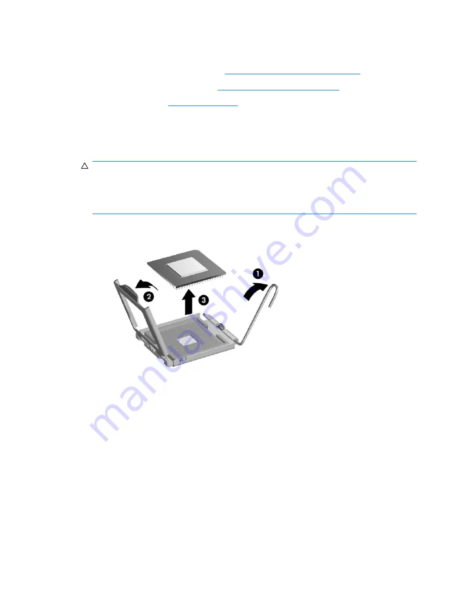
Rotate the locking lever to its full open position 

(1)

.

5.

Raise and rotate the microprocessor retainer to its fully open position 

(2)

.

6.

Carefully lift the processor from the socket 

(3)

.

CAUTION:

Do NOT handle the pins in the processor socket. These pins are very fragile and

handling them could cause irreparable damage. Once pins are damaged it may be necessary to
replace the system board.

The heatsink must be installed within 24 hours of installing the processor to prevent damage to the
processor’s solder connections.

To install a new processor:

1.

Place the processor in its socket and close the retainer.

2.

Secure the locking lever.

If reusing the existing heatsink, go to step 3.

If using a new heatsink, go to step 5.

3.

If reusing the existing heatsink, apply the thermal grease provided in the spares kit to the top of
the processor.

4.

Clean the bottom of the heatsink with the provided alcohol pad and place it atop the processor.

Processor

61

Содержание Compaq dx2450

Страница 1: ...Service Reference Guide HP Compaq dx2450 Business PC ...

Страница 2: ...companying such products and services Nothing herein should be construed as constituting an additional warranty HP shall not be liable for technical or editorial errors or omissions contained herein This document contains proprietary information that is protected by copyright No part of this document may be photocopied reproduced or translated to another language without the prior written consent ...

Страница 3: ... 3 Computer Diagnostic Features HP Insight Diagnostics 9 Accessing HP Insight Diagnostics 9 Survey Tab 10 Test Tab 11 Status Tab 11 Log Tab 12 Help Tab 12 Saving and Printing Information in HP Insight Diagnostics 13 Downloading the Latest Version of HP Insight Diagnostics 13 Protecting the Software 13 HP Backup and Recovery Manager 14 4 Serial and Parallel ATA Drive Guidelines and Features SATA Ha...

Страница 4: ...um Coin Cell Battery 25 6 Removal and Replacement Procedures Microtower MT Chassis Serial Number Location 26 Preparation for Disassembly 27 External Security Devices 28 Cable Lock 28 Padlock 28 HP Business PC Security Lock 29 Computer Access Panel 31 Front Bezel 32 Removing Bezel Blanks 33 Cable Management 34 Cable Connections 35 Memory 36 Expansion Cards 39 Drives 43 System Board Drive Connection...

Страница 5: ...tor 73 ATA ATAPI IDE Standard Drive Cable 74 CD ROM 50 Pin Connector 75 24 Pin Power 75 24 Pin MicroFit Power 76 4 Pin Power for CPU 76 6 Pin Power for CPU 76 SATA Data and Power 77 PCI Express 77 PCI Express 78 PCI Express Mini Card 79 DVI Connector 80 Appendix B Power Cord Set Requirements General Requirements 81 Japanese Power Cord Requirements 81 Country Specific Requirements 82 Appendix C Tro...

Страница 6: ...Appendix D System Board and Riser Board Reference Designators 92 Appendix E Specifications Index 100 vi ...

Страница 7: ...has begun DO NOT TURN OFF THE COMPUTER UNTIL THE PROCESS IS COMPLETE Turning off the computer during the installation process may damage the software that runs the computer or prevent its proper installation NOTE If the computer shipped with more than one operating system language on the hard drive the installation process could take up to 60 minutes If your computer was not shipped with a Microso...

Страница 8: ...isc Set immediately before using the computer and schedule regular automatic Recovery Point backups To create the Recovery Disc Set 1 Click Start HP Backup and Recovery HP Backup and Recovery Manager to open the Backup and Recovery Wizard then click Next 2 Select Create a set of recovery discs Recommended and click Next 3 Follow the instructions in the wizard For more information on using HP Backu...

Страница 9: ...up F10 Utility and the settings described in this section Enable or disable removable media boot ability Using Computer Setup F10 Utilities Computer Setup can be accessed only by turning the computer on or restarting the system To access the Computer Setup Utilities menu complete the following steps 1 Turn on or restart the computer 2 As soon as the computer is turned on press F10 when the monitor...

Страница 10: ...ptions may vary depending on the hardware configuration Table 2 1 Computer Setup Main Option Description System Time Allows you to set system time System Date Allows you to set system date Language Allows you to select language Floppy Diskette A Allows you to set drive A to Disabled 1 44 MB 3 5 Not Installed 1st Drive 2nd Drive 3rd Drive 4th Drive For each allows you to view only Capacity Size HDD...

Страница 11: ...etup Advanced Option Description CPU Type view only CPU Speed view only Cache RAM L2 view only Cache RAM L3 view only some models Primary Video Adapter Allows you to select the boot display device when more than 2 video options are offered by the system PCI PCI Ex1 PCI Ex16 Onboard Onboard Video Memory Size 32MB 128MB 256MB PS 2 Mouse Allows you to set Disabled Enabled Auto Detect USB Legacy Mode ...

Страница 12: ...pervisor Password Allows you to change supervisor password User Password Allows you to change the user password Computer Setup Power NOTE Support for specific Computer Setup options may vary depending on the hardware configuration Table 2 3 Computer Setup Power Option Description After AC Power Failure Allows you to select system restart behavior after power loss Auto Power On Stay Off NX Disables...

Страница 13: ...ppy Group Boot Priority Specifies boot device priority within removable devices CD ROM Group Boot Priority Specifies boot device priority within CD DVD drives Hard Drive Group Boot Priority Specifies boot device priority within hard drives Network Group Boot Priority Specifies boot device priority within bootable network devices Computer Setup Exit NOTE Support for specific Computer Setup options ...

Страница 14: ...options to their default values including options for ctrl F10 you must enter F10 Setup mode and press F5 This does not include updates to system date system time supervisor password user password and CPU frequency multiplier 8 Chapter 2 Computer Setup F10 Utility ...

Страница 15: ...recommended after installing or connecting a new device You should run tests save the test results and print them so that you have printed reports available before placing a call to the Customer Support Center NOTE Third party devices may not be detected by HP Insight Diagnostics Accessing HP Insight Diagnostics To access HP Insight Diagnostics you must create a Recovery Disc Set then boot to the ...

Страница 16: ...ories of information to display All Gives a listing of all categories of information about the computer Overview Gives you a listing of general information about the computer Architecture Provides system BIOS and PCI device information Asset Control Shows product name asset tag system serial number and processor information Communication Shows information about the computer parallel LPT and serial...

Страница 17: ... test you want to run Quick Complete or Custom 3 Select the Test Mode Interactive or Unattended 4 Choose how you want the test to be executed either Number of Loops or Total Test Time When choosing to run the test over a specified number of loops enter the number of loops to perform If you desire to have the diagnostic test for a specified time period enter the amount of time in minutes 5 If perfo...

Страница 18: ... the device tested The Test section displays the type of test run The Description section describes the error that the diagnostic test found The Recommended Repair will give a recommended action that should be performed to resolve the failed hardware The Failed Count is the number of times the device has failed a test The Error Code provides a numerical code for the failure The error codes are def...

Страница 19: ...e has been written to the media 5 Print the information from the storage device used to save it NOTE To exit HP Insight Diagnostics click Exit Diagnostics button in the bottom left corner of the screen then remove the CD from the optical drive Downloading the Latest Version of HP Insight Diagnostics 1 Go to http www hp com 2 Click the Software Driver Downloads link 3 Enter your product number for ...

Страница 20: ...ery Disc Set immediately before using the computer and schedule regular automatic Recovery Point backups To create the Recovery Disc Set 1 Click Start HP Backup and Recovery HP Backup and Recovery Manager to open the Backup and Recovery Wizard then click Next 2 Select Create a set of recovery discs Recommended and click Next 3 Follow the instructions in the wizard For more information on using HP ...

Страница 21: ...ive voltages 3 3 V 5 V 12 V Jumpers for configuring drive N A Data transfer rate 3 0 Gb s SATA connectors on the system board are color coded to make identification easier SATA Identification Color Port Attachment Sequence Primary channel device 0 Dark blue SATA 0 1 Primary channel device 1 Light Blue SATA 2 4 Secondary channel device 0 White SATA 1 2 Secondary channel device 1 Orange SATA 3 3 NOT...

Страница 22: ... grounds and 4 transmit receive pins Pin Number Usage Device Plug Host Plug P1 Ground Ground Ground P2 A Transmit data Receive data P3 A Transmit data Receive data P4 Ground Ground Ground P5 B Receive data Transmit data P6 B Receive data Transmit data P7 Ground Ground Ground P2 and P3 differential signal pair P5 and P6 differential signal pair SATA Power Cable Pin Usage Notes Pin Usage Notes P1 V3...

Страница 23: ... and the operating system used in the computer determines the maximum usable size of a drive partition A drive partition is the largest segment of a drive that may be properly accessed by the operating system A single hard drive may therefore be subdivided into a number of unique drive partitions in order to make use of all of its space Because of the differences in the way that drive sizes are ca...

Страница 24: ...this chapter is essential for proper service CAUTION When the computer is plugged into an AC power source voltage is always applied to the system board You must disconnect the power cord from the power source before opening the computer to prevent system board or component damage Chassis Designation Microtower MT 18 Chapter 5 Identifying the Chassis Routine Care and Disassembly Preparation ...

Страница 25: ...7 500 V 3 000 V 400 V 400 V 15 000 V 5 000 V 800 V 700 V 35 000 V 12 000 V 6 000 V 2 000 V Removing DIPs from vinyl tray Removing DIPs from Styrofoam Removing bubble pack from PCB Packing PCBs in foam lined box 2 000 V 3 500 V 7 000 V 5 000 V 4 000 V 5 000 V 20 000 V 11 000 V 11 500 V 14 500 V 26 500 V 21 000 V These are then multi packaged inside plastic tubes trays or Styrofoam NOTE 700 volts ca...

Страница 26: ...the Work Area To prevent static damage at the work area use the following precautions Cover the work surface with approved static dissipative material Provide a wrist strap connected to the work surface and properly grounded tools and equipment Use static dissipative mats foot straps or air ionizers to give added protection Handle electrostatic sensitive components parts and assemblies by the case...

Страница 27: ...mputer by blocking any vents or air intakes Do not place the keyboard with the keyboard feet down directly against the front of the desktop unit as this also restricts airflow Occasionally clean the air vents on all vented sides of the computer Lint dust and other foreign matter can block the vents and limit the airflow Be sure to unplug the computer before cleaning the air vents Never operate the...

Страница 28: ...bborn stains use isopropyl rubbing alcohol No rinsing is needed as the alcohol will evaporate quickly and not leave a residue After cleaning always wipe the unit with a clean lint free cloth Occasionally clean the air vents on the computer Lint and other foreign matter can block the vents and limit the airflow Cleaning the Keyboard Follow all safety precautions in General Cleaning Safety Precautio...

Страница 29: ...the mouse ensure that the power to the computer is turned off Clean the mouse ball by first removing the retaining plate and the ball from the housing Pull out any debris from the ball socket and wipe the ball with a clean dry cloth before reassembly To clean the mouse body follow the procedures in Cleaning the Computer Case on page 22 Service Considerations Listed below are some of the considerat...

Страница 30: ... snagged by parts being removed or replaced CAUTION When servicing this computer ensure that cables are placed in their proper location during the reassembly process Improper cable placement can damage the computer Hard Drives Handle hard drives as delicate precision components avoiding all physical shock and vibration This applies to failed drives as well as replacement spares If a drive must be ...

Страница 31: ...There is a risk of fire and chemical burn if the battery is handled improperly Do not disassemble crush puncture short external contacts dispose in water or fire or expose it to temperatures higher than 140ºF 60ºC Do not attempt to recharge the battery NOTE Batteries battery packs and accumulators should not be disposed of together with the general household waste In order to forward them to recyc...

Страница 32: ...n the Diagnostics utility to verify that all components operate properly NOTE Not all features listed in this guide are available on all computers Serial Number Location Each computer has a unique serial number and product ID number that are located on the top of the computer Keep these numbers available for use when contacting customer service for assistance 26 Chapter 6 Removal and Replacement P...

Страница 33: ...ways present on the system board as long as the system is plugged into an active AC outlet In some systems the cooling fan is on even when the computer is in the Standby or Suspend modes The power cord should always be disconnected before servicing a unit 6 Disconnect the power cord from the electrical outlet and then from the computer 7 Disconnect all peripheral device cables from the computer 8 ...

Страница 34: ...ing security devices are used to prevent unauthorized access to the internal components of the computer and or secure the computer to a fixed object Cable Lock Padlock 28 Chapter 6 Removal and Replacement Procedures Microtower MT Chassis ...

Страница 35: ...HP Business PC Security Lock 1 Fasten the security cable by looping it around a stationary object 2 Thread the keyboard and mouse cables through the lock External Security Devices 29 ...

Страница 36: ...g the screw provided 4 Insert the plug end of the security cable into the lock 1 and push the button in 2 to engage the lock Use the key provided to disengage the lock 30 Chapter 6 Removal and Replacement Procedures Microtower MT Chassis ...

Страница 37: ...nel ensure that the computer is turned off and that the power cord is disconnected from the electrical outlet 2 Loosen the screw 1 that secures the access panel to the computer chassis 3 Slide the access panel back 2 about 1 3 cm 1 2 inch then lift it off the unit To install the access panel reverse the removal procedure Computer Access Panel 31 ...

Страница 38: ...panel Computer Access Panel on page 31 3 Press outward on the three latches on the right side of the bezel 1 then rotate the right side of the bezel off the chassis 2 followed by the left side To reinstall the front bezel reverse the removal procedure 32 Chapter 6 Removal and Replacement Procedures Microtower MT Chassis ...

Страница 39: ...ed before installing a drive To remove a bezel blank 1 Remove the front bezel 2 To remove a 5 25 inch blank break the blank out of the bezel 1 or To remove a 3 25 inch blank press the two tabs on the left side of the blank 2 toward the right and then pull the blank inward to remove it 3 3 Replace the front bezel Removing Bezel Blanks 33 ...

Страница 40: ...ny cable sharply A sharp bend can break the internal wires Never bend a SATA data cable tighter than a 30 mm 1 18 in radius Never crease a SATA data cable Do not rely on components like the drive cage power supply or computer cover to push cables down into the chassis Always position the cables to lay properly by themselves When removing the power supply power cables from the P1 or P3 connectors o...

Страница 41: ... black Front power button LED F_USB1 white Front I O USB F_USB2 black Media card reader F_AUDIO yellow Front I O audio SPEAKER white Internal speaker XMM1 XMM2 XMM3 XMM4 black black blue blue Memory slots PCI 1 white PCI 2 3 full height slot PCIE_X1_1 black PCI Express X1 slot PCIE_X1_2 black PCI Express X1 slot PCIE X16 black PCI Express X16 slot PROCESSOR silver Processor CMOS PW black with blue...

Страница 42: ...lt DDR2 SDRAM DIMMs The DDR2 SDRAM DIMMs must also support CAS latency 5 DDR2 667 Mhz 5 5 5 timing CAS latency 5 DDR2 800 Mhz 5 5 5 timing and CAS latency 6 DDR2 800 Mhz 6 6 6 timing contain the mandatory JEDEC SPD information In addition the computer supports 512Mbit and 1Gbit non ECC memory technologies single sided and double sided DIMMs DIMMs constructed with x8 and x16 DDR devices DIMMs const...

Страница 43: ...de If this system had two additional DIMMs added into the blue sockets they could be a pair of 512MBor 1024MB DIMMs and the system would still operate in dual channel mode For purposes of like sizes a single sided 512MB DIMM and a double sided 512MB DIMM would not be the same size because they have different numbers of memory chips on them The system will operate in single channel mode if the DIMM...

Страница 44: ...Access Panel on page 31 3 Open both latches of the memory module socket 1 and insert the memory module into the socket 2 NOTE A memory module can be installed in only one way Match the notch on the module with the tab on the memory socket A DIMM must occupy the black XMM1 socket NOTE For maximum performance populate the sockets so that the memory capacity is spread as equally as possible between C...

Страница 45: ...expansion slot 3 PCI Express x1 expansion slot 4 PCI Express x16 expansion slot NOTE You can install a PCI Express x1 x4 x8 or x16 expansion card in the PCI Express x16 expansion slot To remove replace or add an expansion card 1 Prepare the computer for disassembly Preparation for Disassembly on page 27 2 Remove the computer access panel Computer Access Panel on page 31 3 Locate the correct vacant...

Страница 46: ...r the existing expansion card NOTE Before removing an installed expansion card disconnect any cables that may be attached to the expansion card a If you are installing an expansion card in a vacant socket you must use a flatblade screwdriver to pry out the metal shield on the rear panel that covers the expansion slot Be sure to remove the appropriate shield for the expansion card you are installin...

Страница 47: ... socket away from the card and carefully rock the card back and forth until the connectors pull free from the socket Be sure not to scrape the card against the other components 6 Store the removed card in anti static packaging 7 If you are not installing a new expansion card install an expansion slot cover to close the open slot CAUTION After removing an expansion card you must replace it with a n...

Страница 48: ...talling an expansion card press firmly on the card so that the whole connector seats properly in the expansion card slot 9 Replace the slot cover lock and secure it in place with the screw that was previously removed 10 Connect external cables to the installed card if needed Connect internal cables to the system board if needed 11 Reconfigure the computer if necessary Refer to the Computer Setup F...

Страница 49: ... next available unpopulated SATA connector on the system board in the following order SATA0 SATA1 SATA3 SATA2 Connect a diskette drive to the connector labeled FLOPPY Connect a media card reader to the USB connector labeled F_USB2 The system does not support Parallel ATA PATA optical drives or PATA hard drives You may install either a third height or a half height drive into a half height bay If n...

Страница 50: ...rting a drive Avoid exposing a hard drive to liquids temperature extremes or products that have magnetic fields such as monitors or speakers If a drive must be mailed place the drive in a bubble pack mailer or other protective packaging and label the package Fragile Handle With Care System Board Drive Connections Refer to the following illustration and table to identify the system board drive conn...

Страница 51: ... 1 Two 5 25 inch external drive bays for optional drives optical drives shown 2 One 3 5 inch external drive bay for optional drive media card reader shown 3 Primary 3 5 inch internal hard drive bay 4 Secondary 3 5 inch internal hard drive bay for optional hard drive To verify the type and size of the storage devices installed in the computer run Computer Setup Refer to Computer Setup F10 Utility o...

Страница 52: ...r Disassembly on page 27 2 Remove the computer access panel Computer Access Panel on page 31 3 Remove the front bezel Front Bezel on page 32 4 Disconnect the power cable 1 and data cable 2 from the rear of the optical drive 5 Remove the screws that secure the drive to the drive cage 1 then slide the drive out of the front of the chassis 2 46 Chapter 6 Removal and Replacement Procedures Microtower ...

Страница 53: ...otate the screwdriver to break the knockout plate out of the chassis Discard the knockout plate 6 If the new drive has screws installed on the sides of the drive remove the screws before inserting the drive into the chassis 7 Slide the drive in through the front of the chassis 1 until the bezel on the drive is evenly aligned with the computer front bezel and install the M3 metric retainer screws 2...

Страница 54: ... Removing an External 3 5 inch Drive CAUTION All removable media should be taken out of a drive before removing the drive from the computer NOTE The 3 5 inch drive bay may contain a diskette drive or a media card reader 1 Prepare the computer for disassembly Preparation for Disassembly on page 27 2 Remove the computer access panel Computer Access Panel on page 31 3 Remove the front bezel Front Bez...

Страница 55: ...d in the following illustrations a If you are removing a diskette drive disconnect the data cable 1 and power cable 2 from the back of the drive b If you are removing a media card reader disconnect the USB cable from the system board Drives 49 ...

Страница 56: ...ge 32 4 If you are installing a diskette drive or media card reader in a bay covered by a bezel blank remove the front bezel then remove the bezel blank See Removing Bezel Blanks on page 33 for more information 5 If you are adding a drive to an empty drive bay for the first time you must remove the knockout plate from the bay To do so insert a flat screwdriver into the knockout plate slot and rota...

Страница 57: ...ppropriate drive cables a If installing a diskette drive connect the power and data cables to the rear of the drive and connect the other end of the data cable to the connector on the system board labeled FLOPPY b If installing a media card reader connect the USB cable from the media card reader to the USB connector on the system board labeled F_USB2 NOTE Refer to System Board Drive Connections on...

Страница 58: ...that were preinstalled on the computer If you do not have this CD set select Start HP Backup and Recovery and create it now 1 Prepare the computer for disassembly Preparation for Disassembly on page 27 2 Remove the computer access panel Computer Access Panel on page 31 3 Remove the two screws that secure the hard disk drive cage to the chassis 4 Push down the latch on the side of the hard disk dri...

Страница 59: ...5 Lift the hard disk drive cage out of the chassis 6 Disconnect the power cable 1 and data cable 2 from the back of the hard drive Drives 53 ...

Страница 60: ...rd disk drive out of the hard disk drive cage 2 Installing an Internal 3 5 inch Hard Drive 1 Follow the steps in Removing an Internal 3 5 inch Hard Drive on page 52 to remove the hard drive cage and if necessary the existing hard drive 54 Chapter 6 Removal and Replacement Procedures Microtower MT Chassis ...

Страница 61: ... are replacing an old drive with a new drive use the four retainer screws from the old drive to install the new drive NOTE If you are installing a second hard drive use four of the extra standard 6 32 screws that are installed on the interior of the front bezel The 6 32 screws are silver 3 Connect the power cable 1 and data cable 2 to the back of the hard drive CAUTION Never crease or bend a SATA ...

Страница 62: ...ur system has only one SATA hard drive you must connect the hard drive data cable to the dark blue connector labeled SATA0 to avoid any hard drive performance problems If you are adding a second hard drive connect the data cable to the next available unpopulated SATA connector on the system board in the following order SATA0 SATA1 SATA3 SATA2 7 Replace the computer access panel 8 Lock any security...

Страница 63: ...Access Panel on page 31 3 Remove the front bezel Front Bezel on page 32 4 Disconnect the front USB cable from the yellow system board connector F_AUDIO and the I O cable from the white system board connector F_USB1 5 Stand the unit upright 6 Remove the silver T15 screw 1 that secures the panel to the chassis 7 Pull the panel 2 away from the unit while threading the wires between the drive cage and...

Страница 64: ... remove the cable 7 To remove the power button assembly perform the following steps simultaneously a On the right side of the assembly press down on the top tab 1 b Press in on the tab on the right side of the assembly 2 c While pressing the two tabs pull the assembly away from the chassis enough to loosen the tabs from their slots in the chassis 8 Pull the assembly away from the chassis while thr...

Страница 65: ...e the tab on the backplate and then press the latch toward the heatsink to disengage the metal hook on the opposite side of the heatsink from the backplate 6 Lift the heatsink from the processor 7 Remove the heatsink from the processor When reinstalling the heatsink make sure that its bottom has been cleaned with an alcohol wipe and fresh thermal grease has been applied to the top of the processor...

Страница 66: ... from the system board 1 Remove the four silver Phillips screws that secure the backplate to the system board 2 Remove the backplate from the system board 60 Chapter 6 Removal and Replacement Procedures Microtower MT Chassis ...

Страница 67: ...handling them could cause irreparable damage Once pins are damaged it may be necessary to replace the system board The heatsink must be installed within 24 hours of installing the processor to prevent damage to the processor s solder connections To install a new processor 1 Place the processor in its socket and close the retainer 2 Secure the locking lever If reusing the existing heatsink go to st...

Страница 68: ... BIOS is being used on the computer The latest system BIOS can be found on the Web at http h18000 www1 hp com support files Speaker 1 Prepare the computer for disassembly Preparation for Disassembly on page 27 2 Remove the computer access panel Computer Access Panel on page 31 3 Remove the front bezel Front Bezel on page 32 4 Disconnect the wire from the white system board connector labeled SPEAKE...

Страница 69: ...er for disassembly Preparation for Disassembly on page 27 2 Remove the computer access panel Computer Access Panel on page 31 3 Disconnect the fan control cable from the red system board connector labeled SYS_FAN1 4 From the outside remove the four silver Phillips screws that secure the fan to the chassis 5 Lift the fan out of the chassis To install the fan assembly reverse the removal procedure B...

Страница 70: ...cables from the drives and from the system board 4 Remove the four silver T15 screws that connect the power supply to the chassis 5 While pressing the tab in front of the power supply that holds it in place pull the power supply up slightly to loosen it from the chassis 6 Lift the power supply out of the chassis 64 Chapter 6 Removal and Replacement Procedures Microtower MT Chassis ...

Страница 71: ...stallation 5 Remove the heatsink Heatsink on page 59 6 Remove the remaining eight screws that secure the system board to the chassis 7 Slide the system board toward the front of the computer to disengage the I O panel from the rear of the chassis 8 Lift the system board out of the computer When reinstalling the system board first insert the I O panel back into the slots in the rear of the chassis ...

Страница 72: ...on backing up the CMOS settings Static electricity can damage the electronic components of the computer or optional equipment Before beginning these procedures ensure that you are discharged of static electricity by briefly touching a grounded metal object NOTE The lifetime of the lithium battery can be extended by plugging the computer into a live AC wall socket The lithium battery is only used w...

Страница 73: ...me and any special system setups using Computer Setup Refer to Computer Setup F10 Utility on page 3 Type 2 Battery Holder 1 To release the battery from its holder squeeze the metal clamp 1 that extends above one edge of the battery When the battery pops up lift it out 2 To insert the new battery slide one edge of the replacement battery under the holder s lip with the positive side up 2 Push the o...

Страница 74: ...n the clip 1 that holds the battery in place then remove the battery 2 2 Insert the new battery and position the clip back in place 3 Replace the computer access panel 4 Plug in the computer and turn on power to the computer 5 Reset the date and time and any special system setups using Computer Setup Refer to Computer Setup F10 Utility on page 3 68 Chapter 6 Removal and Replacement Procedures Micr...

Страница 75: ... Some of these connectors may not be used on the product being serviced Keyboard Connector and Icon Pin Signal 1 2 3 Data Unused Ground 4 5 6 5 VDC Clock Unused Mouse Connector and Icon Pin Signal 1 2 3 Data Unused Ground 4 5 6 5 VDC Clock Unused Ethernet BNC Connector and Icon Pin Signal 1 2 Data Ground Keyboard 69 ...

Страница 76: ...Pin Signal Pin Signal 1 2 3 4 Ground Negative AUI Differential Collision Positive AUI Differential Collision Negative AUI Differential Transmit 9 10 11 12 Positive AUI Differential Receive 12V Ground Ground 5 6 7 8 Positive AUI Differential Transmit Ground Ground Negative AUI Differential Receive 13 14 15 16 Unused Unused Unused Unused 70 Appendix A Connector Pin Assignments ...

Страница 77: ...a Bit 5 Data Bit 6 14 15 16 17 Auto Linefeed Error Initialize Printer Select IN 9 Data Bit 7 18 25 Signal Ground Serial Interface Powered and Non Powered Connector and Icon Pin Signal 1 2 3 Carrier Detect 12V if powered Receive Data Transmit Data 4 5 6 Data Terminal Ready Signal Ground Data Set Ready 7 8 9 Request to Send Clear to Send Ring Indicator 5V if powered Parallel Interface 71 ...

Страница 78: ...ne Connector and Icon 1 8 miniphone Pin Signal 1 2 3 1 Tip 2 Ring 3 Shield Audio_left Power_Right Ground Line in Audio Connector and Icon 1 8 miniphone Pin Signal 1 2 3 1 Tip 2 Ring 3 Shield Audio_In_Left Audio_In_Right Ground Line out Audio Connector and Icon 1 8 miniphone Pin Signal 1 2 3 1 Tip 2 Ring 3 Shield Audio_Out_Left Audio_Out_Right Ground 72 Appendix A Connector Pin Assignments ...

Страница 79: ...e Not Used Not Used Not Used Monitor Connector and Icon Pin Signal Pin Signal 1 2 3 4 Red Analog Green Analog Blue Analog Not used 9 10 11 12 5V fused Ground Not used DDC Serial Data 5 6 7 8 Ground Ground Ground Ground 13 14 15 Horizontal Sync Vertical Sync DDC Serial Clock External Infrared Transceiver 73 ...

Страница 80: ...D14 DD0 DD15 29 30 31 32 DMAK Ground INTRQ IOCS16 5 6 7 8 DD6 DD9 DD5 DD10 19 20 21 22 Ground Key DMARQ Ground 33 34 35 36 DA1 PDIAG cable detect DA0 DA2 9 10 11 12 DD4 DD11 DD3 DD12 23 24 25 26 DIOW Ground DIOR Ground 37 38 39 40 CS1FX CS3FX DASP Ground 13 14 DD2 DD13 27 28 IORDY CSEL 74 Appendix A Connector Pin Assignments ...

Страница 81: ...34 DA1 PDIAG DA0 DA2 44 45 46 47 GND GND GND CSEL 9 10 11 12 13 DD6 DD10 DD5 DD11 DD4 22 23 24 25 26 DMARQ GND DIOR DIOW GND 35 36 37 38 39 CS1FX CS3FX DASP 5V 5V 48 49 50 GND Vendor specific Vendor specific 24 Pin Power Connector 24 12 13 1 Front Pin Signal Pin Signal Pin Signal Pin Signal 1 2 3 4 5 6 3 3V 3 3V GND 5V GND 5V 7 8 9 10 11 12 GND POK 5 Vaux 12V 12V 3 3V 13 14 15 16 17 18 3 3V 12V GN...

Страница 82: ...2 PWRGD 3 3V 3 3V Tach GND Fan CMD 13 14 15 16 17 18 12V 5V Sense GND 5V 5V 3 3V 19 20 21 22 23 24 GND 3 3V Sense 3 3V 3 3V GND 4 Pin Power for CPU Connector and Icon Pin Signal 1 2 3 4 GND GND 12V CPU 12V CPU 6 Pin Power for CPU Connector and Icon Pin Signal 6 4 1 2 3 4 5 6 GND GND GND 12V CPU 12V CPU 12V 76 Appendix A Connector Pin Assignments ...

Страница 83: ...ctor Pin A Pin Signal Pin Signal Pin Signal Pin Signal Pin Signal 1 2 3 4 5 PRSNT1 12V 12V GND JTAG2 6 7 8 9 10 JTAG3 JTAG4 JTAG5 3 3V 3 3V 11 12 13 14 15 PERST GND REFCLK REFCLK GND 16 17 18 19 20 PERp0 PERn0 GND RSVD GND 21 22 23 24 25 PERp1 PERn1 GND GND PERp2 26 27 28 29 30 PERn 2 GND GND PERp3 PERn3 31 32 33 34 35 GND RSVD RSVD GND PERp4 36 37 38 39 40 PERn4 GND GND PERp5 PERn5 41 42 43 44 45...

Страница 84: ...x8 and x16 PCI Express Connector Pin B Pin Signal Pin Signal Pin Signal Pin Signal Pin Signal 1 2 3 4 5 12V 12V RSVD GND SMCLK 6 7 8 9 10 SMDAT GND 3 3 V JTAG1 3 3vAux 11 12 13 14 15 WAKE RSVD GND PETp0 PETn0 16 17 18 19 20 GND GND GND PETp1 PETn1 21 22 23 24 25 GND GND PETp2 PETn2 GND 26 27 28 29 30 GND PETp3 PETn3 GND RSVD 31 32 33 34 35 PRSNT2 GND PETp4 PETn4 GND 36 37 38 39 40 GND PETp5 PETn5 ...

Страница 85: ...1 32 x8 PCI Express uses pins 1 49 x16 PCI Express uses pins 1 8 PCI Express Mini Card PCI Express Mini Card Connector Pin Signal Pin Signal Pin Signal Pin Signal Pin Signal 1 2 3 4 5 6 WAKE 3 3V Reserved GND Reserved 1 5V 7 8 9 10 11 12 CLKREQ UIM_PWR GND UIM_DATA REFCLK UIM_CLK 13 14 15 16 17 18 REFCLK UIM_RESET GND UIM_VPP Reserved UIM_C8 GND 19 20 21 22 23 24 Reserved UIM_C4 W_DISABLE GND PERS...

Страница 86: ...eserved for future UIM interface if needed DVI Connector Connector and Icon Pin Signal Pin Signal 1 2 3 4 T M D S Data2 T M D S Data2 T M D S Data2 4 Shield T M D S Data4 13 14 15 16 T M D S Data3 5V Power Ground for 5V Hot Pug Detect 5 6 7 8 T M D S Data4 DDC Clock DDC Data No Connect 17 18 19 20 T M D S Data0 T M D S Data0 T M D S Data0 5 Shield T M D S Data5 9 10 11 12 T M D S Data1 T M D S Dat...

Страница 87: ...dited agency responsible for evaluation in the country where the power cord set will be installed 2 The power cord set must have a minimum current capacity of 10A 7A Japan only and a nominal voltage rating of 125 or 250 volts AC as required by each country s power system 3 The diameter of the wire must be a minimum of 0 75 mm2 or 18AWG and the length of the cord must be between 1 8 m 6 feet and 3 ...

Страница 88: ... fittings appliance coupler and wall plug must bear the certification mark of the agency responsible for evaluation in the country where it will be used 2 The flexible cord must be Type SVT or equivalent No 18 AWG 3 conductor The wall plug must be a two pole grounding type with a NEMA 5 15P 15A 125V or NEMA 6 15P 15A 250V configuration 3 Appliance coupler flexible cord and wall plug must bear a T ...

Страница 89: ...Listen for a series of beeps from the computer The beeps are error codes that will help you diagnose the problem Refer to Interpreting POST Audible Codes on page 90 to interpret the codes If the screen is blank plug the monitor into a different video port on the computer if one is available Or change out the monitor with a monitor that you know is functioning properly If you are working on a netwo...

Страница 90: ...onitor are plugged into a working electrical outlet Check to see that the voltage select switch some models is set to the appropriate voltage for your region 115V or 230V Check to see that the computer is turned on and the power light is on Check to see that the monitor is turned on and the green monitor light is on Turn up the brightness and contrast controls of the monitor if the monitor is dim ...

Страница 91: ...ervice provider Computer will not turn on Cause Solution Cables to the external power source are unplugged Ensure that cables connecting the computer to the external power source are plugged in properly and the wall outlet is active Voltage selector switch on rear of computer chassis some models not switched to correct line voltage 115V or 230V Select the proper AC voltage using the selector switc...

Страница 92: ...battery or contact an authorized dealer or reseller for RTC battery replacement Cursor will not move using the arrow keys on the keypad Cause Solution The Num Lock key may be on Press the Num Lock key The Num Lock light should not be on if you want to use the arrow keys The Num Lock key can be disabled or enabled in Computer Setup Poor performance is experienced Cause Solution Processor is hot 1 M...

Страница 93: ...tion Cause unknown Restart the computer Blank screen no video Cause Solution Monitor is not turned on and the monitor light is not on Turn on the monitor and check that the monitor light is on The cable connections are not correct Check the cable connection from the monitor to the computer and to the electrical outlet You may have a screen blanking utility installed or energy saver features are en...

Страница 94: ... still has power Power off the computer and remove the power cord before proceeding A new device is not recognized as part of the system Cause Solution Device is not seated or connected properly Ensure that the device is properly and securely connected and that pins in the connector are not bent down Cable s of new external device are loose or power cables are unplugged Ensure that all cables are ...

Страница 95: ...documentation that came with the system to determine if you are using the correct memory modules and to verify the proper installation 2 Listen for beeps from the computer See Interpreting POST Audible Codes on page 90 to determine possible causes 3 If you still cannot resolve the issue contact Customer Support Solving Hardware Installation Problems 89 ...

Страница 96: ...ce the system board 3 short beeps and 1 long beep followed by a three second pause CPU configuration error or invalid CPU detected before graphics card initialized 1 Upgrade the BIOS to proper version 2 Change the processor 1 short beep followed by a one second pause No legacy floppy drive or optical drive found 1 Check cable connections 2 Run the Computer Setup utility and ensure the device port ...

Страница 97: ...ou visit http www hp com NOTE If you take the computer to an authorized reseller dealer or service provider for service remember to provide the setup and power on passwords if they are set Refer to the number listed in the warranty or in the Support Telephone Numbers guide for technical assistance Contacting Customer Support 91 ...

Страница 98: ...drive activity LED Boot block header jumper Boot block recovery header ROM recovery header CPLD programming header Clear Password header jumper E50 J7 J9 J10 J11 Clear CMOS header RJ45 jack Stacked RJ45 Dual USB Quad stacked USB First IEEE 1394 connector J12 J13 J14 J20 29 J30 Second IEEE 1394 connector SPDIF input SPDIF output PCI slots PCI extender slot male J31 J35 J37 PCI Express slots Primary...

Страница 99: ...deo connector VGA Primary single USB connector Secondary single USB port Microphone jack J73 J74 J75 J76 J77 Line in jack Line out jack Headphone jack Volume control Double stacked headphone Bottom microphone Top connector J78 J80 J81 J82 J83 Double stacked line in Top line out Bottom connector Stacked serial audio connector Primary double stack USB Top Port 2 Bottom Port 1 Secondary double stack ...

Страница 100: ...5 P16 P17 Alert on LAN connector VRM module footprint AUI connector Fan command fan sink header may be 2 or 4 pin Digital audio expansion header P18 P19 P20 P21 P22 SPDIF internal input header SPDIF internal output header Primary IDE connector Secondary IDE MultiBay connector Header for NEWCARD P23 P24 P25 P26 P27 Header for front panel audio Header for front panel USB Internal USB connector 1 Int...

Страница 101: ...PU fan header for fansink P80 P81 P82 P83 P84 Primary Serial Attached SCSI SAS connector Second Serial Attached SCSI SAS connector Third Serial Attached SCSI SAS connector Fourth Serial Attached SCSI SAS connector Fifth Serial Attached SAS connector P85 P86 P87 P101 P106 Sixth Serial Attached SAS connector Seventh Serial Attached SAS connector Eighth Serial Attached SAS connector Security board co...

Страница 102: ...VRM controller USB front port power switch First USB rear port power switch Second USB rear port power switch U53 XBT XMM1 XMM2 XMM5 XU1 Third USB rear port power switch Battery retainer Memory slot DIMM1 or RIMM1 populated and tested Following memory slots Primary processor socket XU2 XU15 U15 XU19 U19 Y1 Y2 Secondary processor socket System ROM and Socket Socket XU15 ROM U15 SPI ROM and socket X...

Страница 103: ...Y4 Y5 H5 Secondary NIC clock crystal RTC clock crystal tie down 97 ...

Страница 104: ... Operating Nonoperating 7 500 ft 15 000 ft 2286 m 4572 m NOTE Operating temperature is derated 1 0 C per 300 m 1000 ft to 3000 m 10 000 ft above sea level no direct sustained sunlight Maximum rate of change is 10 C Hr The upper limit may be limited by the type and number of options installed Heat Dissipation Maximum Typical idle 1575 BTU hr 307 BTU hr 397 kg cal hr 77 kg cal hr Power Supply Operat...

Страница 105: ...rrected power supply The power factor correction is present in the 230V operating mode only This allows the system to pass the CE mark requirements for use in the countries of the European Union This supply requires the use of an input voltage range select switch Table E 1 Specifications continued 99 ...

Страница 106: ...tion 27 diskette drive installing 50 removing 48 drive connectors 44 drives locations 45 DVI pin assignments 80 E electrostatic discharge ESD preventing damage 19 ethernet AUI pin assignments 70 BNC pin assignments 69 RJ 45 pin assignments 70 expansion cards removal and replacement 39 expansion slot cover removing 40 replacing 41 external security 28 F fan power supply 23 front bezel removal and r...

Страница 107: ...ear chassis fan 63 speaker 62 system board 65 removing bezel blanks 33 diskette drive 48 expansion slot cover 40 hard drive 52 media card reader 48 optical drive 46 PCI card 41 PCI Express card 41 riser board reference designators 92 S safety precautions cleaning 22 SATA connectors on system board 15 data cable pinouts 16 hard drive characteristics 15 pin assignments 77 power cable pinouts 16 scre...

Отзывы: