4.
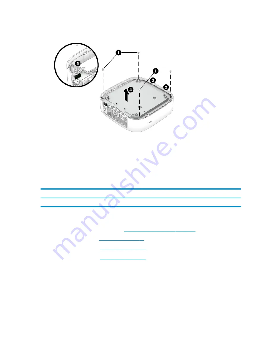
Disconnect the power connector cable from the system board connector (5).
5.
Remove the bottom shield.
To replace the bottom shield, reverse the removal procedures.
Power connector cable
To remove the power connector cable, use these procedures and illustrations.
Table 6-4
Power connector cable description and part number
Description
Spare part number
Power connector cable
L17259-001
Before removing the power connector cable, follow these steps:
1.
Prepare the Chromebox for disassembly (
Preparation for disassembly on page 27
2.
Remove the bottom cover (
3.
Remove the I/O side frame (
).
4.
Remove the bottom shield (
Remove the power connector cable:
1.
Turn the bottom shield right side up with the rear panel toward you.
2.
Remove the two Phillips M2.5 × 5.0 screws (1) that secure the power connector cable to the bottom shield.
3.
Remove the power connector cable bracket (2).
The power connector cable bracket is available using spare part number M42090-001.
4.
Remove the power connector cable (3).
30
Chapter 6 Removal and replacement procedures for authorized service provider parts
ENWW
Содержание Chromebox G3
Страница 8: ...4 Chapter 1 Product description ENWW ...
Страница 16: ...12 Chapter 2 Getting to know your Chromebox ENWW ...
Страница 20: ...16 Chapter 3 Illustrated parts catalog ENWW ...
Страница 24: ...20 Chapter 4 Removal and replacement procedures preliminary requirements ENWW ...
Страница 46: ...42 Chapter 6 Removal and replacement procedures for authorized service provider parts ENWW ...
Страница 50: ...46 Chapter 7 Specifications ENWW ...
Страница 54: ...50 Chapter 8 Power cord set requirements ENWW ...
Страница 56: ...52 Chapter 9 Recycling ENWW ...


