background image


Component identification  71 

Component identification 

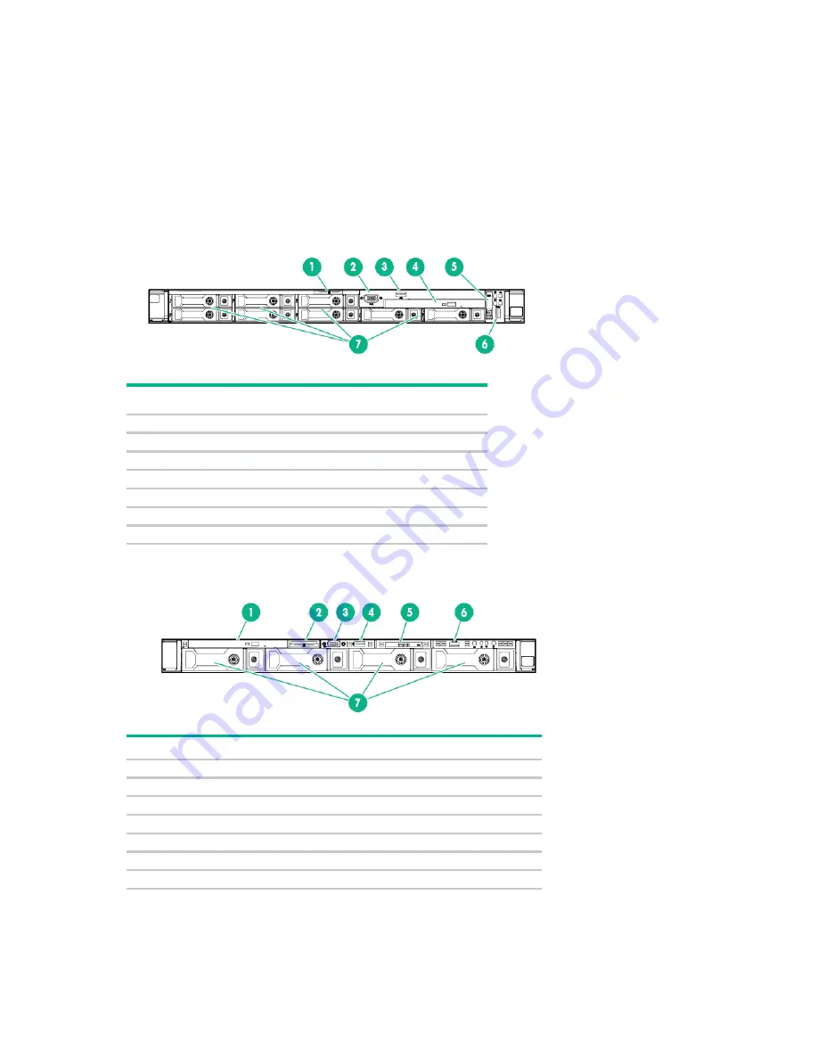
Front panel components 


8SFF 


Item  Description 

Serial label pull tab 

Front video connector (optional) 

USB 2.0 connector (optional) 

Optical drive (optional) 

Systems Insight Display (optional) 

USB 3.0 connector 

SAS/SATA/SSD drive bays 


4LFF 


Item 

Description 

Optical drive (optional) 

Serial label pull tab 

Front video connector (optional) 

USB 2.0 connector (optional) 

Systems Insight Display (optional) 

USB 3.0 connector 

SAS/SATA/SSD drive bays 


Содержание 780019-S01

Страница 1: ...pecifications and requirements for hardware components and software This guide is for an experienced service technician Hewlett Packard Enterprise assumes you are qualified in the servicing of computer equipment trained in recognizing hazards in products and are familiar with weight and stability precautions Part Number 767928 006 March 2016 Edition 6 ...

Страница 2: ...in Links to third party websites take you outside the Hewlett Packard Enterprise website Hewlett Packard Enterprise has no control over and is not responsible for information outside the Hewlett Packard Enterprise website Microsoft and Windows are either registered trademarks or trademarks of Microsoft Corporation in the United States and or other countries Intel Pentium and Itanium are trademarks...

Страница 3: ...cess panel 26 Primary PCI riser cage 26 PCIe riser board 27 Secondary PCI riser cage 28 Primary PCIe riser blank 29 Secondary PCIe riser blank 30 GPU riser and cable option 31 Fan module 32 Fan blank 33 8SFF Optical USB VGA assembly 34 4LFF Optical USB VGA assembly 35 8SFF Systems Insight Display 37 4LFF Systems Insight Display 38 Location discovery services ear 39 2SFF SAS SATA drive cage assembl...

Страница 4: ... 86 Cabling overview 86 2SFF embedded SATA backplane cabling 86 4LFF Universal Media Bay cabling 87 8SFF Universal Media Bay cabling 88 10SFF 6 NVMe 4 SAS SATA Express Bay Enablement Option cabling 89 Smart Array controller cabling 90 Embedded SATA cabling 91 M 2 SSD Enablement Board option cabling 92 GPU cabling 93 Specifications 94 Environmental specifications 94 Server specifications 94 Power s...

Страница 5: ...r Customer self repair 1 Access panel 775425 001 Mandatory1 2 PCI riser blank a PCI riser blank full height 775431 001 Mandatory1 b PCI riser blank low profile 785499 001 Mandatory1 3 PCI riser cage a PCI riser cage standard primary 775421 001 Optional2 b PCI riser cage secondary full height 775419 001 Optional2 c PCI riser cage secondary low profile 775420 001 Optional2 4 Miscellaneous blanks kit...

Страница 6: ...ewlett Packard Enterprise dépendent du type de service de garantie désigné pour votre produit 3 Non Certaines pièces Hewlett Packard Enterprise ne sont pas conçues pour être remplacées par le client Afin de se conformer aux exigences de la garantie la garantie du client Hewlett Packard Enterprise demande à un fournisseur de services agréé de procéder au remplacement de la pièce Ces pièces sont sig...

Страница 7: ...ackard Enterprise vraagt deze onderdelen te vervangen worden er reis en arbeidskosten voor deze service in rekening gebracht 2 Optioneel Onderdelen die de klant zelf kan vervangen Deze onderdelen zijn ook ontworpen om door de klant zelf te worden vervangen Als u Hewlett Packard Enterprise verzoekt om deze te vervangen kan het zijn dat hiervoor extra kosten in rekening worden gebracht afhankelijk v...

Страница 8: ...r board 775419 001 Optional2 10 Controller options a HPE Smart Array P440ar Controller 775413 001 Mandatory1 b HPE Smart Array P440ar Controller with cut heatsink 786760 001 Mandatory1 c HPE H240ar Smart Host Bus Adapter 749997 001 Mandatory1 d HPE Smart Array P840ar Controller 848147 001 Mandatory1 11 Heatsink a Standard efficiency heatsink 775403 001 Optional2 b High performance heatsink 775404 ...

Страница 9: ...5 2603 v4 processor 835599 001 Optional2 t 1 70 GHz Intel Xeon E5 2609 v4 processor 835600 001 Optional2 u 2 40 GHz Intel Xeon E5 2620 v4 processor 835601 001 Optional2 v 2 20 GHz Intel Xeon E5 2630 v4 processor 835602 001 Optional2 w 2 40 GHz Intel Xeon E5 2640 v4 processor 835603 001 Optional2 x 2 20 GHz Intel Xeon E5 2650 v4 processor 835604 001 Optional2 y 2 00 GHz Intel Xeon E5 2660 v4 proces...

Страница 10: ...ly BRDWL 843307 001 Optional2 15 Hot plug fans a Standard fan module 775415 001 Mandatory1 b High efficiency fan module 775416 001 Mandatory1 16 Hot plug power supplies a 500 W Flex Slot Platinum 754377 001 Mandatory1 b 800 W Flex Slot Platinum 754381 001 Mandatory1 c 800 W Flex Slot Titanium 754378 001 Mandatory1 d 800 W Flex Slot Universal 754379 001 Mandatory1 e 800 W Flex Slot 48Vdc 754382 001...

Страница 11: ...E SFF 12G 741226 001 Mandatory1 d 400 GB SAS HE SFF 12G 741232 001 Mandatory1 e 800 GB SAS VE SFF 12G 762749 001 Mandatory1 f 800 GB SAS ME SFF 12G 741228 001 Mandatory1 g 800 GB SAS HE SFF 12G 741234 001 Mandatory1 h 800 GB SAS VE LFF 12G 762750 001 Mandatory1 i 800 GB SAS ME LFF 12G 692163 001 Mandatory1 j 1 6 TB SAS VE SFF 12G 762751 001 Mandatory1 k 1 6 TB SAS VE LFF 12G 762752 001 Mandatory1 ...

Страница 12: ...F 765059 001 Mandatory1 d 800 GB NVMe LE SFF 765064 001 Mandatory1 e 800 GB NVMe ME SFF 765060 001 Mandatory1 f 1 2 TB NVMe VE SFF 765068 001 Mandatory1 g 1 6 TB NVMe LE SFF 765065 001 Mandatory1 h 1 6 TB NVMe ME SFF 765061 001 Mandatory1 i 2 0 TB NVMe VE SFF 765069 001 Mandatory1 j 2 0 TB NVMe LE SFF 765066 001 Mandatory1 k 2 0 TB NVMe ME SFF 765062 001 Mandatory1 22 Systems Insight Display power...

Страница 13: ...4 001 Mandatory1 g 4LFF x4 Mini SAS cable for P440ar and H240ar 780425 001 Mandatory1 h 2SFF H240ar internal SAS cable 787305 001 Mandatory1 i 2SFF P440ar internal SAS cable 787306 001 Mandatory1 j 8SFF P440ar internal SAS cable 787307 001 Mandatory1 k 4LFF P440ar internal SAS cable 787308 001 Mandatory1 l GPU cable secondary riser 780426 001 Mandatory1 m GPU cable primary riser 780427 001 Mandato...

Страница 14: ...sgelegt Um den Garantieanspruch des Kunden zu erfüllen muss das Teil von einem Hewlett Packard Enterprise Servicepartner ersetzt werden Im illustrierten Teilekatalog sind diese Teile mit No bzw Nein gekennzeichnet 1 Obligatorio Componentes cuya reparación por parte del usuario es obligatoria Si solicita a Hewlett Packard Enterprise que realice la sustitución de estos componentes tendrá que hacerse...

Страница 15: ...Illustrated parts catalog 15 ...

Страница 16: ...rver from the rack on page 17 If the rack environment cabling configuration or the server location in the rack creates awkward conditions remove the server from the rack Power down the server Before powering down the server for any upgrade or maintenance procedures perform a backup of critical server data and programs IMPORTANT When the server is in standby mode auxiliary power is still being prov...

Страница 17: ...re that the rack is adequately stabilized before extending a component from the rack WARNING To reduce the risk of personal injury be careful when pressing the server rail release latches and sliding the server into the rack The sliding rails could pinch your fingers 5 After performing the installation or maintenance procedure slide the server into the rack a Slide the server fully into the rack b...

Страница 18: ...ct rear panel release the cable management arm and swing the arm away from the rack as indicated Access the Systems Insight Display To access the optional pop out HPE Systems Insight Display 1 Press and release the panel 2 After the display fully ejects rotate the display to view the LEDs ...

Страница 19: ...Removal and replacement procedures 19 8SFF ...

Страница 20: ...when setting up the system or handling parts A discharge of static electricity from a finger or other conductor may damage system boards or other static sensitive devices This type of damage may reduce the life expectancy of the device To prevent electrostatic damage Avoid hand contact by transporting and storing products in static safe containers Keep electrostatic sensitive parts in their contai...

Страница 21: ...cted the potential for injury exists WARNING To reduce the risk of injury from a hot component allow the surface to cool before touching 12 25 kg 15 31 kg 27 00 lb 33 76 lb This symbol indicates that the component exceeds the recommended weight for one individual to handle safely WARNING To reduce the risk of personal injury or damage to the equipment observe local occupational health and safety r...

Страница 22: ...il it locks into place Hot plug SAS SATA drives and SSDs CAUTION To prevent improper cooling and thermal damage do not operate the server unless all bays are populated with either a component or a blank To remove the component 1 Back up all server data on the drive 2 Determine the status of the drive from the drive LED definitions Hot plug drive LED definitions on page 83 3 Remove the drive To rep...

Страница 23: ... has completed and ceased signal traffic flow can cause loss of data To remove the component 1 Press the Power button The Do Not Remove button LED illuminates and flashes Do not press the button while the LED is illuminated 2 When the Do Not Remove button LED is no longer flashing or illuminated press the Do Not Remove button to open the release lever 3 Remove the drive To replace the component 1 ...

Страница 24: ... any unused drive bays Power supply blank Remove the component as indicated To replace the component reverse the removal procedure AC power supply CAUTION To prevent improper cooling and thermal damage do not operate the server unless all bays are populated with either a component or a blank ...

Страница 25: ...cool before touching it To replace the component reverse the removal procedure HPE 750W Flex Slot Hot Plug Battery Backup Module CAUTION To prevent improper cooling and thermal damage do not operate the server unless all bays are populated with either a component or a blank To remove the component 1 Access the product rear panel on page 18 2 If the FSBBU is cabled to a second FSBBU disconnect the ...

Страница 26: ...nel to the rear of the chassis and remove the access panel To replace the component 1 Place the access panel on top of the server with the hood latch open Allow the panel to extend past the rear of the server approximately 1 25 cm 0 5 inch 2 Push down on the hood latch The access panel slides to a closed position Primary PCI riser cage CAUTION To prevent damage to the server or expansion boards po...

Страница 27: ...nnect each power cord from the server 3 Do one of the following o Extend the server from the rack on page 17 o Remove the server from the rack on page 17 4 Remove the access panel Access panel on page 26 5 Remove the PCIe riser cage o Primary PCIe riser cage Primary PCI riser cage on page 26 2SFF Express Bay drive backplane on page 44 o Secondary PCIe riser cage Secondary PCI riser cage on page 28...

Страница 28: ...er down the server and remove all AC power cords before removing or installing the PCI riser cage 1 Power down the server on page 16 2 Remove all power a Disconnect each power cord from the power source b Disconnect each power cord from the server 3 Do one of the following o Extend the server from the rack on page 17 o Remove the server from the rack on page 17 4 Remove the access panel Access pan...

Страница 29: ...ot cover or an expansion board installed To remove the component 1 Power down the server on page 16 2 Remove all power a Disconnect each power cord from the power source b Disconnect each power cord from the server 3 Do one of the following o Extend the server from the rack on page 17 o Remove the server from the rack on page 17 4 Remove the access panel Access panel on page 26 5 Remove the PCI ri...

Страница 30: ...erver unless all PCI slots have either an expansion slot cover or an expansion board installed To remove the component 1 Power down the server on page 16 2 Remove all power a Disconnect each power cord from the power source b Disconnect each power cord from the server 3 Do one of the following o Extend the server from the rack on page 17 o Remove the server from the rack on page 17 4 Remove the ac...

Страница 31: ... risk of personal injury from hot surfaces allow the drives and the internal system components to cool before touching them CAUTION To prevent damage to electrical components properly ground the server before beginning any installation procedure Improper grounding can cause ESD 1 Back up all server data 2 Power down the server on page 16 3 Do one of the following o Extend the server from the rack ...

Страница 32: ...PU support bracket 7 Disconnect the GPU riser cable from the GPU and the primary riser cage PCA GPU cabling on page 93 8 Remove the GPU from the 16x slot in the primary PCI riser cage position To replace the component reverse the removal procedure Fan module The server supports up to seven standard or high performance fans Install fans 1 and 2 only when processor 2 is installed When only one proce...

Страница 33: ...d to compensate CAUTION To avoid server shutdown a fan must be replaced within 60 seconds of being removed 3 Remove the fan module To replace the component reverse the removal procedure Fan blank Install fans 1 and 2 only when processor 2 is installed When only one processor is installed install the fan blanks in bays 1 and 2 To remove the component 1 Extend the server from the rack on page 17 2 R...

Страница 34: ...component 1 Power down the server on page 16 2 Remove all power a Disconnect each power cord from the power source b Disconnect each power cord from the server 3 Do one of the following o Extend the server from the rack on page 17 o Remove the server from the rack on page 17 4 Remove the access panel Access panel on page 26 5 Disconnect the optical drive cable ...

Страница 35: ...ove the component 1 Power down the server on page 16 2 Remove all power a Disconnect each power cord from the power source b Disconnect each power cord from the server 3 Do one of the following o Extend the server from the rack on page 17 o Remove the server from the rack on page 17 4 Remove the access panel Access panel on page 26 5 Disconnect the cables ...

Страница 36: ...Removal and replacement procedures 36 o Optical drive cabling o USB VGA cabling 6 Remove the assembly ...

Страница 37: ...sight Display To remove the component 1 Power down the server on page 16 2 Remove all power a Disconnect each power cord from the power source b Disconnect each power cord from the server 3 Do one of the following o Extend the server from the rack on page 17 o Remove the server from the rack on page 17 4 Remove the access panel Access panel on page 26 ...

Страница 38: ...e screw securing the Systems Insight Display and then remove the Systems Insight Display To replace the component reverse the removal procedure 4LFF Systems Insight Display To remove the component 1 Power down the server on page 16 2 Remove all power a Disconnect each power cord from the power source b Disconnect each power cord from the server 3 Do one of the following o Extend the server from th...

Страница 39: ...disconnect the USB cable from the front of the Systems Insight Display 6 Remove the screw securing the Systems Insight Display and then remove the Systems Insight Display To replace the component reverse the removal procedure Location discovery services ear To remove the component 1 Power down the server on page 16 2 Remove all power a Disconnect each power cord from the power source b Disconnect ...

Страница 40: ...server from the rack on page 17 o Remove the server from the rack on page 17 4 Remove the access panel Access panel on page 26 5 Remove the hot plug fan or fan blank from fan bay 1 Fan module on page 32 6 Disconnect the discovery services cable 7 Remove the discovery cable cover ...

Страница 41: ... drives and the internal system components to cool before touching them CAUTION To prevent damage to electrical components properly ground the server before beginning any installation procedure Improper grounding can cause ESD 1 Back up all server data 2 Power down the server on page 16 3 Do one of the following o Extend the server from the rack on page 17 o Remove the server from the rack on page...

Страница 42: ...Removal and replacement procedures 42 5 Remove the universal media bay blank 6 Install the drive cage assembly and then tighten the three screws ...

Страница 43: ...rage drive connector and the backplane presence detect connector 8 Connect the power cable to the left power connector on the backplane CAUTION To prevent improper cooling and thermal damage do not operate the server or the enclosure unless all drive and device bays are populated with either a component or a blank ...

Страница 44: ...system installation Improper grounding can cause electrostatic discharge To remove the component 1 Back up all server data 2 Remove all power a Disconnect each power cord from the power source b Disconnect each power cord from the server 3 Do one of the following o Extend the server from the rack on page 17 o Remove the server from the rack on page 17 4 Remove the access panel Access panel on page...

Страница 45: ...le from the left power connector on the backplane 7 Disconnect the data cables on the Express bay drive cage from port 3 on the Express bay bridge card 8 Remove the primary PCI riser cage Primary PCI riser cage on page 26 2SFF Express Bay drive backplane on page 44 ...

Страница 46: ...he removal procedure 4LFF hard drive backplane To remove the component 1 Power down the server on page 16 2 Remove all power a Disconnect each power cord from the power source b Disconnect each power cord from the server 3 Do one of the following o Extend the server from the rack on page 17 o Remove the server from the rack on page 17 4 Remove the access panel Access panel on page 26 ...

Страница 47: ...ckplane To remove the component 1 Power down the server on page 16 2 Remove all power a Disconnect each power cord from the power source b Disconnect each power cord from the server 3 Do one of the following o Extend the server from the rack on page 17 o Remove the server from the rack on page 17 4 Remove the access panel Access panel on page 26 5 Remove all hot plug hard drives Hot plug SAS SATA ...

Страница 48: ...c discharge To remove the component 1 Back up all server data 2 Remove all power a Disconnect each power cord from the power source b Disconnect each power cord from the server 3 Do one of the following o Extend the server from the rack on page 17 o Remove the server from the rack on page 17 4 Remove the access panel Access panel on page 26 5 Remove all drives and drive blanks 6 Disconnect all pow...

Страница 49: ...Express Bay drive backplane on page 44 To replace the component reverse the removal procedure FlexibleLOM To remove the component 1 Power down the server on page 16 2 Remove all power a Disconnect each power cord from the power source b Disconnect each power cord from the server 3 Disconnect the LAN segment cables 4 Do one of the following o Extend the server from the rack on page 17 ...

Страница 50: ...e Smart Storage Battery To remove the component 1 Power down the server on page 16 2 Remove all power a Disconnect each power cord from the power source b Disconnect each power cord from the server 3 Do one of the following o Extend the server from the rack on page 17 o Remove the server from the rack on page 17 4 Remove the access panel Access panel on page 26 ...

Страница 51: ...xpansion boards supported with this server include any board installed in the PCIe riser board assembly controllers and the Express Bay bridge card To remove the component 1 Power down the server on page 16 2 Remove all power a Disconnect each power cord from the power source b Disconnect each power cord from the server 3 Do one of the following o Extend the server from the rack on page 17 ...

Страница 52: ...e riser cage back into the server M 2 SSD enablement board To remove the component 1 Power down the server on page 16 2 Remove all power a Disconnect each power cord from the power source b Disconnect each power cord from the server 3 Do one of the following o Extend the server from the rack on page 17 o Remove the server from the rack on page 17 4 Remove the access panel Access panel on page 26 5...

Страница 53: ...e PCIe riser cage before installing the PCIe riser cage back into the server DIMMs To remove the component 1 Power down the server on page 16 2 Remove all power a Disconnect each power cord from the power source b Disconnect each power cord from the server 3 Do one of the following o Extend the server from the rack on page 17 o Remove the server from the rack on page 17 4 Remove the access panel A...

Страница 54: ...nd must be replaced if the heatsink is removed from the processor after it has been installed CAUTION To avoid thermal shutdown all fans must be installed in a dual processor configuration To remove the component 1 Power down the server on page 16 2 Remove all power a Disconnect each power cord from the power source b Disconnect each power cord from the server 3 Do one of the following o Extend th...

Страница 55: ... reusable and must be replaced if the heatsink is removed from the processor after it has been installed CAUTION To avoid thermal shutdown all fans must be installed in a dual processor configuration To remove the component 1 Power down the server on page 16 2 Remove all power a Disconnect each power cord from the power source b Disconnect each power cord from the server 3 Do one of the following ...

Страница 56: ...socket cover and a heatsink blank or a processor and a heatsink IMPORTANT Processor socket 1 must always be populated If processor socket 1 is empty the server does not power up Depending on the memory configuration and processor model the memory speed may run at 1600MHz 1866MHz or 2133MHz To remove the component 1 Update the system ROM Locate and download the latest ROM version from the Hewlett P...

Страница 57: ...essor retaining bracket 7 Remove the processor from the processor retaining bracket CAUTION To avoid damage to the processor do not touch the bottom of the processor especially the contact area To replace the component CAUTION To avoid damage to the system board processor socket and screws do not overtighten the heatsink screws ...

Страница 58: ...ARE VERY FRAGILE AND EASILY DAMAGED To avoid damage to the system board do not touch the processor or the processor socket contacts 2 Close the processor retaining bracket When the processor is installed properly inside the processor retaining bracket the processor retaining bracket clears the flange on the front of the socket CAUTION Do not press down on the processor Pressing down on the process...

Страница 59: ...you may need to replace the battery that provides power to the real time clock WARNING The computer contains an internal lithium manganese dioxide a vanadium pentoxide or an alkaline battery pack A risk of fire and burns exists if the battery pack is not properly handled To reduce the risk of personal injury Do not attempt to recharge the battery Do not expose the battery to temperatures higher th...

Страница 60: ...or more information about battery replacement or proper disposal contact an authorized reseller or an authorized service provider System board To remove the component 1 Power down the server on page 16 2 Remove all power a Disconnect each power cord from the power source b Disconnect each power cord from the server 3 Do one of the following o Extend the server from the rack on page 17 o Remove the...

Страница 61: ...n page 49 11 Remove all DIMMs DIMMs on page 53 12 Disconnect all cables connected to the system board 13 Remove the heatsink Heatsink on page 54 14 Remove the processor Processor on page 56 15 Loosen the system board thumbscrews 16 Remove the system board using the handle to lift it out of the chassis ...

Страница 62: ...oval and replacement procedures 62 To replace the component 1 Install the spare system board 2 Open each of the processor locking levers in the order indicated and then open the processor retaining bracket ...

Страница 63: ...on the processor Pressing down on the processor may cause damage to the processor socket and the system board Press only in the area indicated on the processor retaining bracket CAUTION Close and hold down the processor cover socket while closing the processor locking levers The levers should close without resistance Forcing the levers closed can damage the processor and socket requiring system bo...

Страница 64: ...a indicated on the processor retaining bracket 7 Install the processor socket cover on the failed system board 8 Clean the old thermal grease from the heatsink and the top of the processor with the alcohol swab Allow the alcohol to evaporate before continuing 9 Apply all the grease to the top of the processor in the following pattern to ensure even distribution ...

Страница 65: ...ppears The serial number should only be modified by qualified service personnel This value should always match the serial number located on the chassis 4 Press the Enter key to clear the warning 5 Enter the serial number and press the Enter key 6 Select Product ID The following warning appears Warning The Product ID should ONLY be modified by qualified service personnel This value should always ma...

Страница 66: ...acement procedures 66 If you suspect a TPM board failure leave the TPM installed and remove the system board Contact a Hewlett Packard Enterprise authorized service provider for a replacement system board and TPM board ...

Страница 67: ... Gen9_TSG_es German http www hpe com support Gen9_TSG_de Japanese http www hpe com support Gen9_TSG_ja Simplified Chinese http www hpe com support Gen9_TSG_zh_cn The HPE ProLiant Gen9 Troubleshooting Guide Volume II Error Messages provides a list of error messages and information to assist with interpreting and resolving error messages on ProLiant servers and server blades To view the guide select...

Страница 68: ...e Health System users operations finances customers employees partners or data center such as IP addresses host names user names and passwords Active Health System does not parse or change operating system data from third party error event log activities such as content created or passed through by the operating system The data that is collected is managed according to the Hewlett Packard Enterpri...

Страница 69: ...te of the host server Download the Active Health System log Register for HPE remote support Use iLO Federation to manage multiple servers from one system running the iLO web interface Use Virtual Power and Virtual Media from the GUI the CLI or the iLO scripting toolkit for many tasks including the automation of deployment and provisioning Control iLO 4 by using a remote management tool For more in...

Страница 70: ...nute granularity You can view recorded events in the IML in several ways including the following From within HPE SIM From within UEFI System Utilities From within the Embedded UEFI shell From within operating system specific IML viewers o For Windows IML Viewer o For Linux IML Viewer Application From within the iLO web interface From within Insight Diagnostics ...

Страница 71: ...nal 3 USB 2 0 connector optional 4 Optical drive optional 5 Systems Insight Display optional 6 USB 3 0 connector 7 SAS SATA SSD drive bays 4LFF Item Description 1 Optical drive optional 2 Serial label pull tab 3 Front video connector optional 4 USB 2 0 connector optional 5 Systems Insight Display optional 6 USB 3 0 connector 7 SAS SATA SSD drive bays ...

Страница 72: ...k active Off No network activity 4 UID button LED Solid blue Activated Flashing blue 1 Hz cycle per sec Remote management or firmware upgrade in progress 4 Hz cycle per sec iLO manual reboot sequence initiated 8 Hz cycle per sec iLO manual reboot sequence in progress Off Deactivated When all four LEDs described in this table flash simultaneously a power fault has occurred For more information see ...

Страница 73: ...stem on Flashing green 1 Hz cycle per sec Performing power on sequence Solid amber System in standby Off No power present When all four LEDs described in this table flash simultaneously a power fault has occurred For more information see Power fault LEDs on page 74 Facility power is not present power cord is not attached no power supplies are installed power supply failure has occurred or the powe...

Страница 74: ...rt SAS HBA controller 6 flashes System board PCIe slots 7 flashes Power backplane or storage backplane 8 flashes Power supply 9 flashes Systems Insight Display LEDs The Systems Insight Display LEDs represent the system board layout The display provides status for all internal LEDs and enables diagnosis with the access panel installed To view the LEDs access the Systems Insight Display Description ...

Страница 75: ...a health event Combinations of illuminated Systems Insight Display LEDs the system power LED and the health LED indicate system status Systems Insight Display LED and color Health LED System power LED Status Processor amber Red Amber One or more of the following conditions may exist Processor in socket X has failed Processor X is not installed in the socket Processor X is unsupported ROM detects a...

Страница 76: ...through hot plug addition Power cap off Amber Standby Power cap green Flashing green Waiting for power Power cap green Green Power is available Power cap flashing amber Amber Power is not available IMPORTANT If more than one DIMM slot LED is illuminated further troubleshooting is required Test each bank of DIMMs by removing all other DIMMs Isolate the failed DIMM by replacing each DIMM in a bank w...

Страница 77: ...g managed remotely Off Identification is deactivated 2L iLO 4 standard NIC activity LED Solid green Activity exists Flashing green Activity exists Off No activity exists 2R iLO 4 standard NIC link LED Solid green Link exists Off No link exists 3 Power supply 2 LED Solid green Normal Off One or more of the following conditions exists AC power unavailable Power supply failed Power supply in standby ...

Страница 78: ...dicates the state of charge of LED flashes State of charge 0 5 1 30 2 31 69 3 70 The state of the LED indicates the FSBBU operating mode LED Mode State Off Ship storage mode Cycle power operating Flashing amber Battery diagnostic Active mode Solid amber Online mode and charger is ON Flashing green Discharge mode RSOC 70 100 frequency 0 5Hz duty 0 5 RSOC 31 69 frequency 1Hz duty 0 5 RSOC 0 30 frequ...

Страница 79: ... maintenance switch 5 Front VGA USB 2 0 connector 6 x4 SATA port 1 7 x4 SATA port 2 8 Backplane presence detect connector 9 Optical SATA port 5 10 SATA port 4 11 Front power USB 3 0 connector 12 HPE Smart Storage Battery connector 13 Optional Location Discovery Services connector 14 Drive backplane power connector 15 microSD card slot 16 Dual internal USB 3 0 connector 17 Smart Array HBA connector...

Страница 80: ...ration information Be sure to properly configure the server or data loss could occur IMPORTANT Before using the S7 switch to change to Legacy BIOS Boot Mode be sure the HPE Dynamic Smart Array B140i Controller is disabled Do not use the B140i controller when the server is in Legacy BIOS Boot Mode NMI jumper The NMI jumper allows administrators to perform a memory dump before performing a hard rese...

Страница 81: ... 8 4 2 1 PCIe3 x8 8 4 2 1 3 LP 3 4L FH PCIe3 x16 16 8 4 2 1 The server ships with one PCIe3 riser cage installed in the primary riser cage connector The x16 PCIe3 riser cage is optional and can be converted to a FH riser This conversion requires a second processor to be installed Notes Primary denotes the riser cage is installed in the primary riser connector Secondary denotes the riser cage is in...

Страница 82: ...ght LP denotes low profile Device numbers 4LFF configuration 8SFF configuration 10SFF configurations With the 10SFF 6 NVMe 4 SAS SATA Express Bay Enablement Option the server supports SAS SATA and PCIe based NVMe drives in the following locations o Bays 1 through 4 support SFF SAS and SATA drives only ...

Страница 83: ...uilding or performing a RAID migration strip size migration capacity expansion or logical drive extension or is erasing Flashing amber green The drive is a member of one or more logical drives and predicts the drive will fail Flashing amber The drive is not configured and predicts the drive will fail Solid amber The drive has failed Off The drive is not configured by a RAID controller NVMe SSD com...

Страница 84: ...n bays 1 and 2 in a single processor configuration The only two valid fan configurations are listed in the following table Configuration Fan bay 1 Fan bay 2 Fan bay 3 Fan bay 4 Fan bay 5 Fan bay 6 Fan bay 7 1 processor Fan blank Fan blank Fan Fan Fan Fan Fan 2 processors Fan Fan Fan Fan Fan Fan Fan For a single processor configuration five fans and two blanks are required in specific fan bays for ...

Страница 85: ... change requires a fan speed increase to cool the server The server shuts down during the following temperature related scenarios At POST and in the OS iLO 4 performs an orderly shutdown if a cautionary temperature level is detected If the server hardware detects a critical temperature level before an orderly shutdown occurs the server performs an immediate shutdown When the Thermal Shutdown featu...

Страница 86: ... hardware options to optimize performance CAUTION When routing cables always be sure that the cables are not in a position where they can be pinched or crimped 2SFF embedded SATA backplane cabling 1 Connect the data cables to the SATA storage connector the SATA optical storage drive connector and the backplane presence detect connector ...

Страница 87: ...ill vary if a PCIe storage controller is installed 4LFF Universal Media Bay cabling Route the cables along the edge of the system board and then connect the cables to the system board 4LFF VGA USB connections Connect the VGA USB cable to the front VGA USB connector toward the rear of the system board 4LFF optical drive connection ...

Страница 88: ...e the cables along the edge of the system board and then connect the cables to the system board 8SFF DVD RW VGA USB connections o Connect the VGA USB cable to the front VGA USB connector toward the rear of the system board o Connect the SATA optical cable to the SATA optical storage drive connector 8SFF VGA USB connections ...

Страница 89: ...t Option cabling The Smart Array P440ar Controller is shown in the cabling diagram but other controllers may be supported For a list of supported controllers see the product QuickSpecs on the Hewlett Packard Enterprise website http www hpe com info qs Item Description 1 Connect the power cable from the 10SFF Express Bay backplane to the system board ...

Страница 90: ...ss Bay backplane to Port 3 on the HPE Express Bay Bridge Card 5 6 Connect the 10SFF Express bay data cable from 10SFF Express Bay backplane to Ports 1 and 2 on the HPE Express Bay Bridge Card If the 2SFF Express Bay Enablement option is not installed then this cable is not required Smart Array controller cabling Connect the SAS SATA cables to the backplane and Smart Array controller Install the SA...

Страница 91: ... installing or replacing any non hot plug hardware option Disconnect all power cords to completely remove power from the server Connect the SATA cables from the backplane to the Mini SAS SATA connectors on the system board according to their labels as Port 1 or Port 2 These labels are on the cables and their connections 8SFF 4LFF ...

Страница 92: ...ne on the system board as indicated on the connectors M 2 SSD Enablement Board option cabling The M 2 SSD enablement board option is supported in both the primary and the secondary PCI riser cage Cable the option according to the location in the server Primary PCI riser cage ...

Страница 93: ...Cabling 93 Secondary PCI riser cage GPU cabling Connect the GPU riser cable to the GPU and the primary riser cage PCA ...

Страница 94: ...ions the supported system inlet temperature range is extended 5 C to 10 C 41 F to 50 F and 35 C to 40 C 95 F to 104 F at sea level with an altitude derating of 1 0 C per every 175 m 1 8 F per every 574 ft above 900 m 2953 ft to a maximum of 3048 m 10 000 ft 40 C to 45 C 104 F to 113 F at sea level with an altitude derating of 1 0 C per every 125 m 1 8 F per every 410 ft above 900 m 2953 ft to a ma...

Страница 95: ...Supply on page 97 HPE 1400W Flex Slot Platinum Plus Hot plug Power Supply on page 98 For detailed power supply specifications see the QuickSpecs on the Hewlett Packard Enterprise website http www hpe com info proliant powersupply HPE 500W Flex Slot Platinum Hot plug Power Supply Specification Value Input requirements Rated input voltage 100 to 127 VAC 200 to 240 VAC 240 VDC for China only Rated in...

Страница 96: ...ina only Power supply output Rated steady state power 800 W at 100 VAC to 127 VAC input 800 W at 200 VAC to 240 VAC input 800 W at 240 VDC input for China only Maximum peak power 800 W at 100 VAC to 127 VAC input 800 W at 200 VAC to 240 VAC input 800 W at 240 VDC input for China only HPE 800W Flex Slot Titanium Plus Hot plug Power Supply Specification Value Input requirements Rated input voltage 2...

Страница 97: ...at 277 VAC 874 W at 380 VDC BTUs per hour 3071 at 200 VAC 3026 at 277 VAC 2982 at 380 VDC Power supply output Rated steady state power 800 W at 200 VAC to 277 VAC input 800 W at 380 VDC input Maximum peak power 800 W at 200 VAC to 277 VAC input 800 W at 380 VDC input HPE 800W Flex Slot 48VDC Hot plug Power Supply Specification Value Input requirements Rated input voltage 40 VDC to 72 VDC 48 VDC no...

Страница 98: ...ng electrode conductor is connected This equipment must be located in the same immediate area such as adjacent cabinets as any other equipment that has a connection between the earthed conductor of the same DC supply circuit and the earthing conductor and also the point of earthing of the DC system The DC system must be earthed elsewhere The DC supply source is to be located within the same premis...

Страница 99: ...arge current 62 50 A Maximum discharge power 750 W Maximum runtime Full load 750 W 75 load 564 W 50 load 375 W 25 load 187 W 60 seconds 145 seconds 220 seconds 300 seconds limited by user Hot plug power supply calculations For hot plug power supply specifications and calculators to determine electrical and heat loading for the server see the Hewlett Packard Enterprise Power Advisor website http ww...

Страница 100: ...Heating Refrigerating and Air Conditioning Engineers CSR Customer Self Repair FLR FlexibleLOM for rack servers FSBBU Flex slot battery backup GPU graphics processing unit HBA host bus adapter HPE SIM HPE Systems Insight Manager IEC International Electrotechnical Commission iLO Integrated Lights Out IML Integrated Management Log LFF large form factor ...

Страница 101: ...nnect Express POST Power On Self Test RBSU ROM Based Setup Utility REST representational state transfer RSOC relative state of change SAS serial attached SCSI SATA serial ATA SD Secure Digital SFF small form factor SPP Standard Parallel Port Mode SSD solid state drive SUV serial USB video TPM Trusted Platform Module ...

Страница 102: ...Acronyms and abbreviations 102 UEFI Unified Extensible Firmware Interface UID unit identification USB universal serial bus VDC voltage direct current ...

Страница 103: ...tion send any errors suggestions or comments to Documentation Feedback mailto docsfeedback hpe com When submitting your feedback include the document title part number edition and publication date located on the front cover of the document For online help content include the product name product version help edition and publication date located on the legal notices page ...

Страница 104: ... location 32 33 fans 32 33 features 71 flex slot battery backup module battery check button 78 flex slot battery backup module LED 78 FlexibleLOM 49 front panel buttons 72 front panel components 71 front panel LEDs 72 FSBBU module 25 99 FSBBU battery check button 78 FSBBU LED 78 G GPU 31 GPU cabling 31 GPU riser board 31 grounding methods 20 grounding requirements 20 H hard drive backplane 46 47 h...

Страница 105: ...ack extending server from 17 20 rear panel buttons 77 rear panel components 76 rear panel LEDs 77 rear panel accessing 18 removal and replacement procedures 16 remove server from rack 17 S safety considerations 20 serial connector 76 Smart Array controller 90 software 69 spare part numbers 5 specifications 94 99 specifications environmental 94 specifications power 95 96 97 98 specifications server...

Отзывы: