49
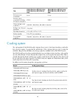
Item
5500-24G-PoE+-4SFP HI (2 slots)/
5500-24G-PoE+-4SFP HI TAA (2
slots)
5500-48G-PoE+-4SFP HI (2 slots)/
5500-48G-PoE+-4SFP HI TAA (2
slots)
Minimum power
consumption
80 W
115 W
Maximum power
consumption (including
PoE power consumption)
950 W
1840 W
Chassis leakage current
compliance
UL60950-1, EN60950-1, IEC60950-1, GB4943
Melting current of power
supply fuse
15A/250V
Operating temperature
0°C to 45°C (32°F to 113°F)
Relative humidity
5% to 95%, noncondensing
Fire resistance
compliance
UL60950-1, EN60950-1, IEC60950-1, GB4943
Cooling system
The cooling system of the 5500 HI switch comprises the air vents in the chassis, fixed fans, and built-in
fans of power supplies. To guarantee the performance of this cooling system, you must consider the
ventilation design for the installation site when you plan the installation site for the 5500 HI switch.
The 5500 HI switch uses fixed fans and left-right aisles for air ventilation. Ambient air flows in through the
air vents at the left side of chassis (the direction subject to the user facing the front panel of the chassis),
circulates through the chassis and the power supplies, and exhausts at the right side of the chassis and
the air outlet vents of the power supplies. The chassis and power supplies use independent aisles, which
must be kept clear when the switch is operating.
For different switch models, design the cooling system as follows:
Model Cooling system design
5500-24G-4SFP HI (2 slots)
5500-48G-4SFP HI (2 slots
5500-24G-SFP HI (2 slots)
5500-24G-SFP HI TAA (2 slots)
Six fans at most, including three fans for the system, one fan for
each power supply, and one for interface card slot SLOT1.
5500-24G-PoE+-4SFP HI (2
slots)
5500-24G-PoE+-4SFP HI TAA
(2 slots)
Four fans at most, including two fans for the system and one fan for
each power supply.
5500-48G-PoE+-4SFP HI (2
slots)
5500-48G-PoE+-4SFP HI TAA
(2 slots)
Five fans at most, including three fans for the system and one fan
for each power supply.


