
9/18/2020
HPE 4200 vl Switch Series - Installation
10/12
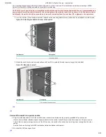
Connect the network devices
The type of network connections user will need to use depends on the typesof switch modules user have installed in 4200vl Switch Series.
See the documentation accompanying the modules for cabling configurations andprocedures for those modules.
In general for all the modules, when a network cable from an active network device is connected to the switch, the Link LED for the switch
port should goon. If the Link LED does not go on, use the table below to help solve the problem, and see the module documentation for
troubleshooting procedures.
Condition
Diagnostic Tip
Port LED isstill off
whena cable is
connected
Try the following procedures:
For the indicated port, verify both ends of the cabling, at the switch and the connected device, aresecurely connected.
Verify the connected device and switch are both powered on and operating correctly.
Verify user have used the correct cable type for the connection:
For all twisted-pair connections, the RJ-45 connectors on the Switch 4200vl Series allow userto use either straight-through cable
or crossover cable when the port is in the Autoconfiguration.
For fiber-optic connections, verify the transmit port on the switch is connected tothe receive port on the connected device, and the
switch receive port is connected tothe transmit port on the connected device.
Verify the port has not been disabled through a switch configuration change.
Verify the connection parameters in the configurations of the switch port and the connected device match. Mismatched configurations are
a frequent cause of connection problems.
User can use the console interface, or, if user have configured an IP address on the switch, use theweb browser interface, or ProCurve
Manager network management software to determine the state and configuration of the port and re-enable the port if necessary.
If the other procedures don’t resolve the problem, try using a different port or a different cable.
top
Connect a console to the switch (Optional)
The switch has a full-featured, easy to use console interface for performing switch management tasks including the following:
Monitor switch and port status and observe network activity statistics
Modify the switch’s configuration.
Read the event log and access diagnostic tools to help in troubleshooting
Download new software to the switch
Add passwords to control access to the switch from the console, web browser interface, and network management stations
The console can be accessed through these methods:
Out-of-band: Connect a PC or VT-100 terminal, to be used as a console,directly to the switch using the serial cable that comes with
the Switch4200vl Series. If the PC or terminal has a 25-pin serial connector, user canuse a readily available 9-pin to 25-pin serial
cable, or attach a 9-to-25 pin straight-through adapter to the PC end of the cable.
In-Band: Access the console using Telnet from a PC or UNIX station onthe network, and a VT-100 terminal emulator. This method
requires that user first configure the switch with an IP address and subnet mask by using either out-of-band console access or
through DHCP/Bootp. For more information on IP addressing, refer to Management and Configuration Guide.
Management and Configuration Guide
The Switch can simultaneously support one out-of-band console sessionthrough the Console Port and one in-band Telnet console
session.
Terminal configuration
To connect a console to the switch, configure the PC terminal emulator as aDEC VT-100 (ANSI) terminal or use a VT-100 terminal, and
configure eitherone to operate with these settings:
Any baud rate from 2400 to 115200 (The switch automatically senses thespeed)
8 data bits, 1 stop bit, no parity, and flow control set to Xon/Xoff
For the Windows Terminal program, also disable (Uncheck) the Usefunction, arrow, and ctrl keys for Windows option
For the Hilgraeve HyperTerminal program, select the Terminal keysoption for the function, arrow, and ctrl keys act as parameter.
If user want to operate the console using a different configuration, make sure user change the settings on both the terminal and on the
switch so they are compatible. Change the switch settings first, save changes, then change the terminal settings, then reboot the switch
and re-establish the consolesession.
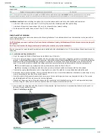
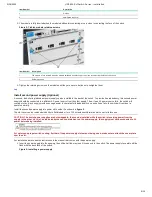
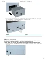
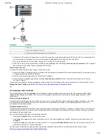
Direct Console access
To connect a console to theswitch, follow these steps:
Figure 13: Direct Console access


