7.
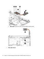
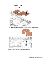
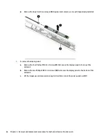
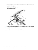
Use the following image to determine proper cable routing around the left hinge for the camera/display
cable and the wireless antenna cables.
(1): Camera cable routing path
(2): Display/camera cable routing path
(3): Antenna cable routing path
8.
If replacing the display enclosure, be sure that the subcomponents (including the camera/microphone
module, the antenna receivers, and all associated cables and hardware) are transferred to the new
enclosure.
Reverse this procedure to reassemble and install the display assembly.
72
Chapter 6 Removal and replacement procedures for Authorized Service Provider parts
Содержание 255 G6
Страница 1: ...HP 255 G6 Notebook PC Maintenance and Service Guide ...
Страница 4: ...iv Safety warning notice ...
Страница 8: ...viii ...
Страница 12: ...4 Chapter 1 Product description ...
Страница 24: ...16 Chapter 2 Components ...
Страница 32: ...24 Chapter 3 Illustrated parts catalog ...
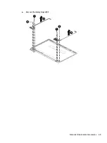
Страница 77: ...e Remove the display hinges 3 Component replacement procedures 69 ...
Страница 100: ...92 Chapter 10 Specifications ...
Страница 110: ...102 Chapter 12 Power cord set requirements ...
Страница 112: ...104 Chapter 13 Recycling ...

