4.
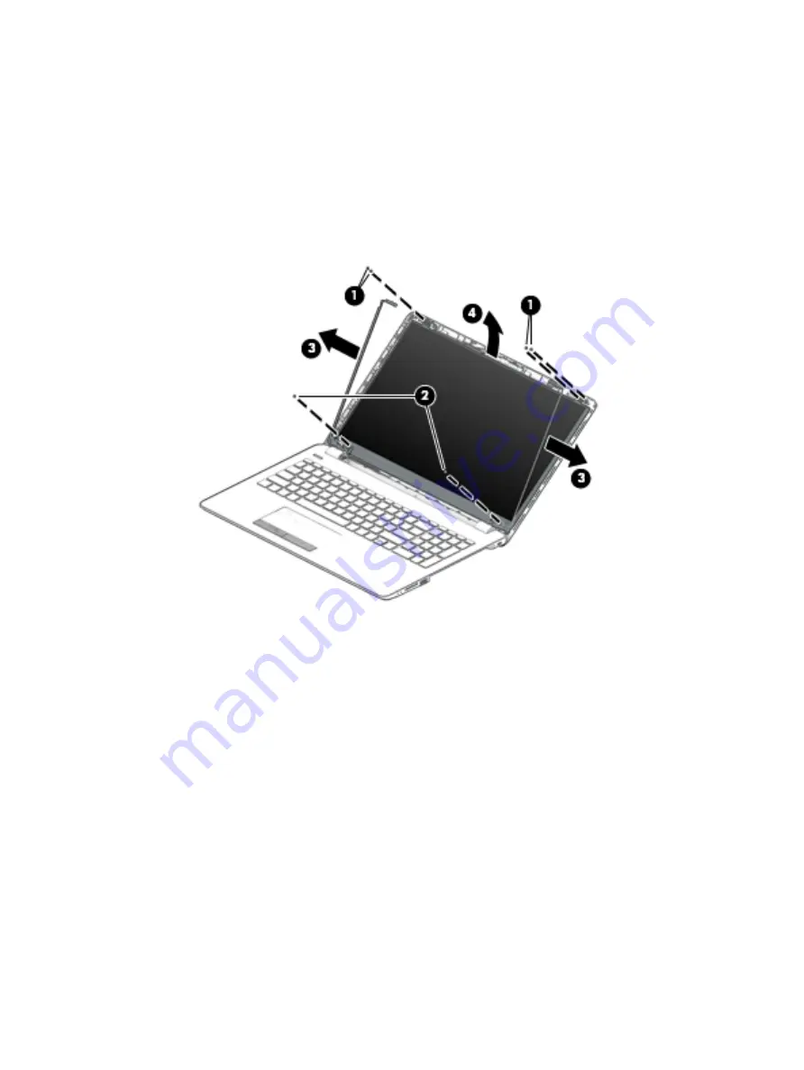
To remove the display panel:
a.
Remove the four Phillips PM2.0×3.0 screws (1) that secure the display panel to the top of the
enclosure.
b.
Remove the two Phillips PM2.0×3.0 screws (2) that secure the display panel to the bottom of the
enclosure.
c.
Lift the hinges up and move aside enough to be able to rotate the panel up and over (3).
d.
Rotate the display panel onto the keyboard (4) to gain access to the display cable connection on
the back of the panel.
e.
On the back of the display panel, release the adhesive strip that secures the display panel cable to
the display panel, and then disconnect the cable (1).
Component replacement procedures
37
Содержание 250 G6
Страница 1: ...HP 250 G6 Notebook PC Maintenance and Service Guide ...
Страница 4: ...iv Safety warning notice ...
Страница 8: ...viii ...
Страница 13: ...Category Description 7th gen Dis 7th gen UMA 6th gen Dis 6th gen UMA Pen Cel UMA Battery Optical drive 5 ...
Страница 14: ...6 Chapter 1 Product description ...
Страница 26: ...18 Chapter 2 Components ...
Страница 88: ...80 Chapter 6 Removal and replacement procedures for Authorized Service Provider parts ...
Страница 106: ...98 Chapter 10 Specifications ...
Страница 116: ...108 Chapter 12 Power cord set requirements ...
Страница 118: ...110 Chapter 13 Recycling ...


