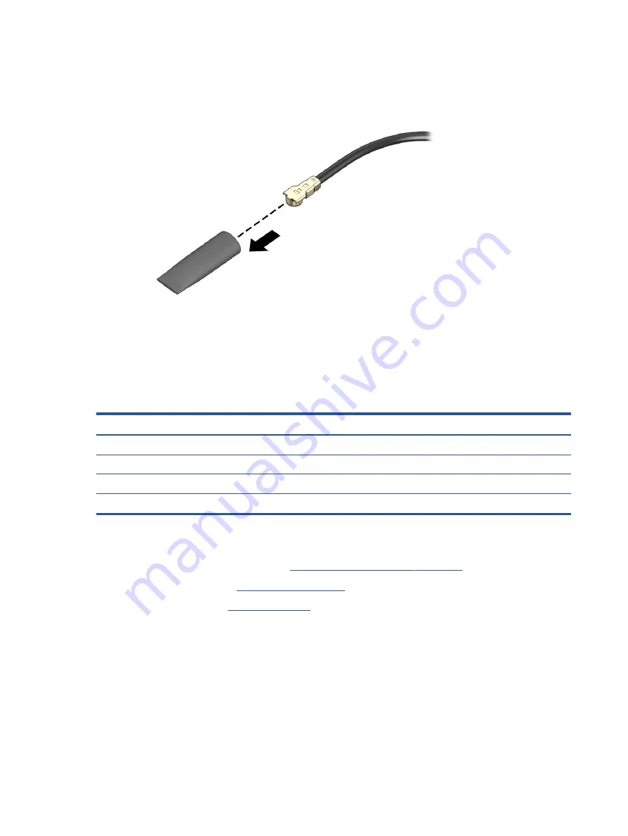
4.
If the WLAN antenna is not connected to the terminal on the WLAN module, a protective sleeve must be
installed on the antenna connector, as shown in the following illustration.
Reverse this procedure to install the WLAN module.
Solid-state drive
To remove the M.2 solid-state drive, use this procedure and illustration.
Table 5-4
Solid-state drive descriptions and part numbers
Description
Spare part number
1 TB, PCIe
L85370-005
512 GB, PCIe
L85364-005
256 GB, PCIe
L85354-005
128 GB, SATA-3, TLC
L85346-005
Before removing the solid-state drive, follow these steps:
1.
Prepare the computer for disassembly (
Preparation for disassembly on page 27
2.
Remove the bottom cover (
).
3.
Remove the battery (see
).
Remove the solid-state drive:
1.
Remove the Phillips M2.0 × 2.5 screw (1) that secures the drive to the computer.
32
Chapter 5 Removal and replacement procedures for authorized service provider parts
Содержание 15-cw1000
Страница 4: ...iv Safety warning notice ...
Страница 8: ...viii ...
Страница 58: ...50 Chapter 5 Removal and replacement procedures for authorized service provider parts ...


