background image

Technical Bulletin 


Page 5 of 8 


Regulating Drive – Complete 


3.22  Readjustment of Maximum 

Working Pressure  

1. 

Stop the control oil unit. 


Warning: 

Depressurize 

hoses/pipes containing high-

pressure fluids and allow them 

to cool to a suitable temperature.


2. 

Dismount the supply and return oil 

hoses at the rotating oil-seal and short-

circuit the two hoses with the nipple 

used previously, see Figure 5. 

3. 

Close the ball valve placed in the 

pressure line just before the outlet 

flange in the oil unit and start the oil unit. 

Readjust the pressure relief valves at 

the control oil pumps at the oil unit 

upwards to the original pressure limit at 

xxx bar (yyyy psi). Check actual value in 

actual set point list in Fan Manual. 

4. 

Stop the oil unit, dismount the short-

circuit valve and mount the supply and 

return oil hoses at the rotating oil-seal. 


3.23  Balancing the Counterweight 

at the Internal Regulating 

Crank Arm 

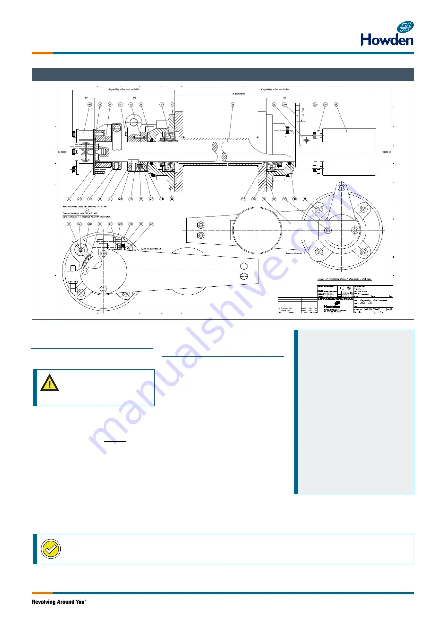
All position numbers refer to drawing 

“Regulating Drive – Complete” in Fan 

Manual. See example above. 
The internal regulating crank arm of the fan is 

equipped with an adjustable counterweight 

(30) mounted on a lever (29). The 

counterweight is mounted to balance the  

spring  inside of the hydraulic cylinder, which 

acts on the pilot valve, forcing it to go out of 

position. If not balanced, hydraulic pressure 

will result in an uncontrolled movement of the 

hydraulic piston. 
Adjustment of the counterweight balancing 

the hydraulic pressure is done from the inside 

of the inner tube of the diffuser. The external 

regulating arm must be disconnected from 

the actuator by disconnecting the connecting 

rod from the external regulating arm. 
 

Balance procedure: 

1. 

Disconnect the external regulating 

arm linkage. 

2. 

Start the control oil unit. 

3. 

Place the internal regulating crank 

arm in a position approximately in 

the middle of the regulating range. 

4. 

Observe if the piston valve moves 

and if so observe the direction. 

5. 

If any movement is observed,  

adjust the counterweight position  

at the lever to increase the force 

applied to the piston valve in the 

opposite direction of the movement. 

6. 

Repeat the adjustment procedure  

by placing the internal regulating 

crank arm in different positions, 

including the end positions. 

7. 

When adjusted stop the control oil 

unit. 


Checkpoint:

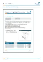
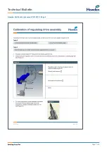
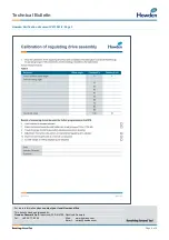
 Calibration of Regulating Drive Assembly in verification document V213351-9. 

Содержание VARIAX B

Страница 1: ...er is transmitted to the external regulating arm of the fan through a connecting rod From the external regulating arm the regulating movements are transmitted to the hydraulic regulating unit hydraulic cylinder through a regulating shaft and a pull fork The position of the actuator in relation to the regulating arm is designed so that the angular motion of the actuator and the air volume are almos...

Страница 2: ...uals 3 21 Calibration of the Regulating Drive Assembly Internal and External Adjustment of the regulating drive assembly is very important to obtain an approximately linear control of the blade pitch This means that the speed of the hydraulic cylinder is constant Regulating Drive geometry is designed so that the torque from the actuator cannot break the external regulating arm activating the torqu...

Страница 3: ... regulate slow increase the pressure relief valve setting until the hub moves Stop the Hydraulics and observe site safety regulations for working on energized equipment and fan blades 1 Dismount one blade and mount the blade adjustment tool onto the blade pivot in the hub See Figure 6 Note the blade pivot number at the verification document V213351 9 2 Start the control oil unit for supplying oil ...

Страница 4: ...anical switches can be adjusted to the position corresponding to the fan stall cancelling angle 17 The internal end of travel limit switches in the actuator should be adjusted according to the supplier s instructions 18 When adjusted the blade angles example in Table 1 should be reached recalculate mA value for stall cancelling for actual blade angles 19 Close the blades carefully to minimum e g 3...

Страница 5: ... adjustable counterweight 30 mounted on a lever 29 The counterweight is mounted to balance the spring inside of the hydraulic cylinder which acts on the pilot valve forcing it to go out of position If not balanced hydraulic pressure will result in an uncontrolled movement of the hydraulic piston Adjustment of the counterweight balancing the hydraulic pressure is done from the inside of the inner t...

Страница 6: ...Technical Bulletin Page 6 of 8 Howden Verification document V213351 9 Page 1 ...

Страница 7: ...Technical Bulletin Page 7 of 8 Howden Verification document V213351 9 Page 2 ...

Страница 8: ...e contact your local Howden office This bulletin has been released by Howden Denmark ApS Industrivej 23 DK 4700 Næstved Denmark Tel 45 55 77 62 62 Web www howden com Email variax howden com Page 8 of 8 Howden Verification document V213351 9 Page 3 ...

Отзывы: