Page 17 of 30
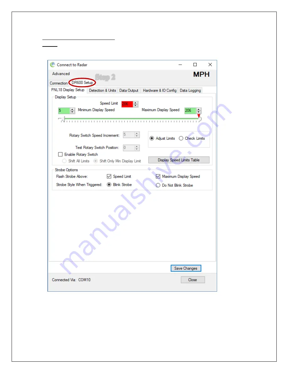
Read The Radar Configuration:
Step 2
: Click on the “DR600 Setup” tab. The software will read the radar configuration
and you should see this screen (actual values will depend on your setup).
Страница 1: ...t Installation and User Manual K Band Doppler Speed Measurement and Display Kit Rev 1 December 20 2021 2005 to 2021 Houston Radar LLC 702 Julie Rivers Drive Sugar Land TX 77478 http www houston radar...
Страница 2: ...to comply with the limits for Class B digital device pursuant to part 15 of the FCC Rules These limits are designed to provide reasonable protection against harmful interference in a residential insta...
Страница 3: ...ration of the device Cet appareil est conforme avec Industrie Canada RSS standard exempts de licence s Son utilisation est soumise Les deux conditions suivantes 1 cet appareil ne peut pas provoquer d...
Страница 4: ...N EXTERNAL CUSTOM MESSAGE 14 LED Driver External Strobe Slow Down Output 14 DR600 Open Drain Outputs 15 COLLECTING AND ANALYZING IN RADAR TRAFFIC STATISTICS 15 REAL TIME TRAFFIC STATISTICS IN THE RADA...
Страница 5: ...ICAL OUTLINE DIMENSIONS 26 APPENDIX A PLASTIC WINDOW LOCATION AND SIZE WHEN USING FRONT METAL MASK 27 APPENDIX B ACTIVATE AN EXTERNAL LED MESSAGE ABOVE A PRESET SPEED 28 APPENDIX C HOUSTON RADAR SLOW...
Страница 6: ...s power efficiency achieved by Low power DR600 radar directly drives display thus eliminating display controller Built in ambient light sensing and automatic brightness control Ambient temperature com...
Страница 7: ...ot be placed right along the side of the road it should be pointed at least 100 150 feet up the road into oncoming traffic The radar in the unit may pick up rotating fans compressor blades etc Avoid p...
Страница 8: ...c have been successfully used as well It does not matter which side into the sign or into the traffic the frosting faces and is left to your discretion 4 Other plastic materials may be used as a front...
Страница 9: ...s Analyzer Measured Speed Output In addition to showing the measured speed on the LED digits the PNL18 will also send out the speed via the ASCII interface as a 3 digit speed with an optional directio...
Страница 10: ...y switch In this case the on board switch must be set to the 0 position or removed at the factory Note 3 To use 3 3V output on pin 13 JMP2 must be shorted Connector Pin Signal Name Direction wrt Radar...
Страница 11: ...PWR Ground 8 DA3 IN OUT Digital input output 3 future expansion 9 VIN PWR Connected to input supply voltage 10 AI1 IN Analog input 1 future expansion 11 Unused Unused Unused pin 12 AI2 IN Analog input...
Страница 12: ...d to input supply voltage Connector Pin Signal Name Direction wrt Radar Description 1 GND PWR Signal PWR Ground 2 VIN OUT Connected to input supply voltage Connector Pin Signal Name Direction wrt Rada...
Страница 13: ...icle is detected between the low speed and high speed limits The display will blink at about 1 4Hz rate if the measured speed is above violator speed This indicates to the driver that they are driving...
Страница 14: ...te PNL18 and display the number 20 bcd 55 1 will change the number to 55 and activate the strobe bcd 55 0 or bcd 55 will turn the strobe off and continue to display 55 bcd 0 will deactivate display an...
Страница 15: ...r and allows the retrieval of stored statistics from the radar by using a PC serial port It also has features to generate traffic reports plot interactive graphs and export the raw data to a MS Excel...
Страница 16: ...onfiguration a snap for the end user Install the Houston Radar Stats Analyzer software provided with the sign on your MS Windows PC After starting the installed program click on Connect To Radar in th...
Страница 17: ...ge 17 of 30 Read The Radar Configuration Step 2 Click on the DR600 Setup tab The software will read the radar configuration and you should see this screen actual values will depend on your setup Step...
Страница 18: ...limits will be fixed skip to next section if sign will be portable unit Step 3B Set the Minimum display speed Display will be blank below this speed Step 3C Set the Maximum display speed Display will...
Страница 19: ...witch important Step 4C Now set the rotary switch increment This increment will apply to all display limits or just to your minimum display speed depending on the rotary switch mode you picked in Step...
Страница 20: ...te above the maximum display speed Strobe light is typically used to draw attention of the driver to the display and the fact that their current vehicle speed is above the posted speed limit or that t...
Страница 21: ...e or disable strobe flashing based on your requirements Step 6B Enable the One s digit option if you have purchased and attached the Houston Radar One s digit panel Step 6C Click the 88 Test button to...
Страница 22: ...o recalibrate the LED driver controller This is to ensure optimal performance and power consumption Step 7 Click the Calibrate button to initiate this process The Status will show Done upon the comple...
Страница 23: ...different measurement units mph kph fps mps and fractional high precision speed output over the serial port If you wish to configure these options click the Detection and Units Data Output Hardware an...
Страница 24: ...FCC Part 15 US Version FCC ID TIADR600 CE Approved IC 21838 DR600 Data Interfaces Serial Communication RS232 Data Rate 1200 to 115200 baud Data Connector DB9 Female with RS232 levels wired as a DCD Us...
Страница 25: ...ing traffic 760 m 2500 feet for larger trucks and vehicles with inherently large radar cross sections In range boost mode or full range mode these values increase to 790 m 2600 feet for compact vehicl...
Страница 26: ...Page 26 of 30 Mechanical Outline Dimensions Rev 1 0 PCB Dimensions in mm Inches...
Страница 27: ...gle is the suggested window size The suggested window is larger than the actual radar because the radar waves diverge at a 9x18 angle from the face of the radar The recommended window size is for a me...
Страница 28: ...e For simplification only two strings are shown on the schematic Then physically arrange the LED s in the form of the message or emoticon you desire The message can be programmed to activate above any...
Страница 29: ...dix C Houston Radar SLOW DOWN panel Houston Radar also offers a SLOW DOWN panel that can simply be plugged into the PNL18 to start operation This panel operates similarly to the LED Message board desc...
Страница 30: ...30 Appendix D Expanding to an Optional 3rd Digit to Make a 3 Digit Speed Sign You may easily expand the PNL18 to a 3rd digit to show the 100 s place value via the optional Houston Radar PNL18 One s d...