


Installation
24
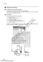
Sensor cable connection
Caution for the sensor cable connection
In handling the sensor cable, pay attention to the following points.
In wiring the sensor cable and the relay cable, keep them away from a motor or any other
inductive device, and their power cables.
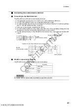
Connections
The sensor cable has the following terminals.
As shown in the following diagram, connect the sensor cable to the terminal block being
careful not to make any mistakes in matching between terminals.
A:
Anode terminal (brown)
R:
Reference electrode terminal (red)
K:
Cathode terminal (orange)
EC:
Electrical cleaning electrode terminal (yellow)
T, T: Temperature compensation terminals (blue and green)
E:
Shield terminal (black)
HR-200
A: Anode electrode terminal (brown)
R: Reference electrode terminal (red)
K: Cathode electrode terminal (orange)
EC: Electrical cleaning electrode terminal (yellow)
T, T: Temperature compensation terminals (green)
T, T: Temperature compensation terminals (blue)
E: Shielded terminal (black)
Residual chlorine sensor
Flow switch (option)
<RA-10/20>
<RA-FS10/20>
h19136 | UTC 2020/03/30 3:34:51
CONFIDENTIAL


