MU1H-1803GE23 R0408
5
Honeywell GmbH
GB
1. Safety Guidelines
1. Follow the installation instructions.
2. Use the appliance
• according to its intended use
• in good condition
• with due regard to safety and risk of danger.
3. Note that the appliance is exclusively for use in the
applications detailed in these installation instruc-
tions. Any other use will not be considered to comply
with requirements and would invalidate the
warranty.
4. Please take note that any assembly, commis-
sioning, servicing and adjustment work may only be
carried out by authorized persons.
5. Immediately rectify any malfunctions which may
influence safety.
2. Functional description
The frost-protected Alwa-Outside Tap is used as
external shut-off valve for potable water installations,
for example as outside tap. The tap is on the outside
and the valve is on the frost-protected inside of the
wall. The outside tap is equipped with an air inelt valve
and a vacuum breaker.
3. Technical data
4. Scope of delivery
The Outside Tap consists of:
• Valve body with connecting elbow and inside
threads according to DIN ISO 2999 to be installed
inside
• Valve cardridge for wall thickness up to 500mm
resp. 800mm
• Copper pipe, tin-plated on inside, diameter 22 x 1
mm
• Fitting with check valve and vacuum breaker accor-
ding to DIN 1988, part 4 and DIN EN 1717
• Anti-twist guard
• Cutting aid
• Protective cap for construction site
• Insulation
5. Assembly
5.1 Wall bushing and inside connection
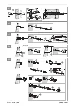
1. Drill bore hole at least Ø 33 with gradient to outside
(at least 2°) through wall
2. Slide anti-twist device over the copper pipe up to the
bend
3. Slide copper pipe with the insulation and protective
cap from the inside to the outside through the wall
and fasten the anti-twist guard with 4 screws to the
wall or in the wall.
4. Connect the pipes inside with connecting bends.
5. Mount the valve cartridge (see chapter 5.3).
6. Plaster the inside wall.
5.2 Removing the valve cartridge
1. Unscrew the protective cap by about 3 rotations,
turn protective cap to middle position and pull off
(bayonet coupling)
2. Pull valve cartridge with hexagon rod out of copper
pipe.
5.3 Mounting the valve cartridge
1. Pull hexagon rod of the valve cartridge until stop to
close the locking claw fasteners.
2. Check whether the backflow preventer has been
plugged in.
3. Feed valve cartridge into the copper pipe with the
hexagon rod and press to stop.
4. Push and turn protective cap onto the copper pipe
(bayonet coupling)
5. Screw in screw until there is a noticeable resistance.
o The valve is closed now.
6. Check the mounted piping.
o Open the water supply.
o No water may leak from the protective cap.
o Check the connected piping for leaks.
Only a gentle turning is needed to close the
valve. Tightening with too much force does
not improve the sealing, but can rather
cause a malfunction.
Remove hoses and screw connections
before the frost period.
Medium
Water and rain water
Operating temperature max. 60 °C
Operating pressure
max. 16 bar (PN 16)
k
vs
-value
2,1 m
3
/h
The valve cartridge needs to be removed
before any soldering work (see chapter 5.2).
After completing the soldering work, the
valve cartridge needs to be remounted (see
chapter 5.3).
Extra force may be needed for this because of
the O-ring pressing.
Содержание V4770
Страница 15: ...Honeywell GmbH 15 MU1H 1803GE23 R0408 PL ...


