Honeywell Thor VM2W Скачать руководство пользователя страница 36

Rev. (a)

Connecting an AC/DC Power Supply

Note:

The Honeywell-approved AC Power Supply and Adapter Cable are only intended for use in a 25ºC (77ºF) maximum

ambient temperature environment.

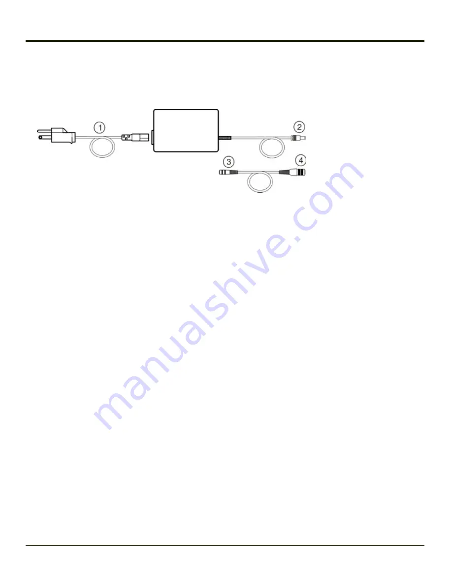
1. AC Input Cable (US only)
2. DC Output Cable
3. To DC Output Cable (see

above)

4. To Thor VM2W

In North America, this unit is intended for use with a UL Listed ITE power supply with output rated 12 – 80VDC, minimum 60W.

Outside North America, this unit is intended for use with an IEC certified ITE power supply with output rated 12 – 80VDC,

minimum 60W.
The external power supply may be connected to either a 120V, 60Hz supply or, outside North America, to a 230V, 50Hz

supply, using the appropriate detachable cordset. In all cases, connect to a properly grounded source of supply provided with

maximum 15 Amp overcurrent protection (10 Amp for 230V circuits).

1. Turn the Thor VM2W off.
2. Connect the detachable cordset provided by Honeywell (US only, all others must provide their own cable) to the

external power supply (IEC 320 connector).

3. Plug cordset into appropriate, grounded, electrical supply receptacle (AC mains).
4. Connect the DC Output Cable end to the power connector on the Thor VM2W Quick Mount.
5. Turn the Thor VM2W on.

3-4

Содержание Thor VM2W

Страница 1: ...Thor VM2W Vehicle Mount Computer Microsoft Windows Embedded Standard Operating System User s Guide ...

Страница 2: ...emarks of Laird Technologies Inc The Bluetooth word mark and logos are owned by the Bluetooth SIG Inc Symbol is a registered trademark of Symbol Technologies MOTOROLA MOTO MOTOROLA SOLUTIONS and the Stylized M Logo are trademarks or registered trademarks of Motorola Trademark Holdings LLC and are used under license RAM and RAM Mount are both trademarks of National Products Inc 1205 S Orr Street Se...

Страница 3: ...hapter 2 Set Up A New Thor VM2W 2 1 Hardware Setup 2 1 Software Setup 2 1 Quick Mount Smart Dock 2 2 Preparing the Dock 2 3 Place the Thor VM2W in the Dock 2 4 Removing the Thor VM2W from the Dock 2 4 Backlights and Indicators 2 5 Display Backlight 2 5 Power Management 2 5 Backlight Brightness 2 5 Screen Blanking 2 5 Keypad Backlight 2 5 LED Functions 2 6 System LEDs 2 7 SYS System Status LED 2 7 ...

Страница 4: ... 2 17 Cleaning the Touch Screen 2 18 Startup Help 2 19 Chapter 3 Connecting Cables to the Thor VM2W 3 1 Connect External Keyboard 3 1 Connect Cable USB Host 3 2 Connect Cable Serial 3 3 Connect a Tethered Scanner 3 3 Connecting an AC DC Power Supply 3 4 Connecting the Headset Cable 3 5 Adjust Headset Microphone and Secure Cable 3 6 Connecting Vehicle Power 3 7 Vehicle 10 60VDC Power Connection 3 7...

Страница 5: ... 3 17 Screen Blanking with Switch 3 18 Fuse 3 18 Chapter 4 Product Agency Compliance Thor VM2W 4 1 Lithium Battery Safety Statement 4 5 Vehicle Power Supply Connection Safety Statement 4 7 Chapter 5 Technical Assistance 5 1 iii ...

Страница 6: ...Rev 01 iv ...

Страница 7: ...puter can easily be moved from one vehicle equipped with a Quick Mount Smart Dock to another vehicle equipped with a Quick Mount Smart Dock The Thor VM2W contains a UPS battery which when fully charged can power the Thor VM2W for a minimum of 30 minutes This can be when the Thor VM2W is not attached to a Quick Mount Smart Dock or when the Thor VM2W is attached to a dock but the vehicle power is in...

Страница 8: ...Rev a Components Front View 1 Power Button 2 Speakers 3 Microphone 1 2 ...

Страница 9: ...ision for Padlock on Thor VM2W 9 Provision for Laptop Security Cable on Thor VM2W 10 Power Switch on Dock 11 Power Connector on Dock 12 Fuse on Dock 13 SD Card Access Panel On Thor VM2W 14 Strain Relief Clamps on Dock 15 RAM Ball on Dock Access Panels Access Panel Door is labeled with SSD and SD 1 CompactFlash Hard Drive 2 SD Secure Digital Memory Card Slot Access Panel Door is labeled with SIM 1 ...

Страница 10: ...n the Blue LED is illuminated the programmable keys are used to adjust speaker volume and display brightness Press the Blue key to enter Blue mode and then press l P1 to Increase speaker volume l P2 to Decrease speaker volume l P3 to Increase display brightness l P4 to Decrease display brightness l No function is assigned to P5 in Blue mode The Blue key has a five second timeout If the Blue key is...

Страница 11: ... function l Orange P1 P6 l Orange P2 P7 etc When the Orange modifier key is active the LED located next to the key is illuminated The modifier key remains active until l The Orange modifier key is pressed again or l A non modifier key is pressed i e P1 P5 or l The Blue modifier key is pressed 1 5 ...

Страница 12: ...cklight is manually controlled Keyboard Backlight The keyboard backlight key in the top right hand corner has a light bulb icon The keyboard keys are backlit The keyboard backlight is manually controlled using the backlight key in the upper right hand corner of the keyboard Pressing the backlight key cycles the keyboard backlight through the levels of backlight intensity Off Low intensity Medium i...

Страница 13: ... UPS battery must be disconnected Please refer to the Thor VM2W Reference Guide for details Hardware Setup 1 Connect accessories to the Quick Mount Smart Dock 2 Connect cables 3 Connect power cable to the dock 4 Secure all cables to the dock with the Strain Relief Cable Clamps 5 Secure the Thor VM2W in the dock 6 Press the power switch on the dock 7 Press the Power key Software Setup Hardware setu...

Страница 14: ...d client connections via an adapter cable l CANbus connection via an adapter cable l Headset connection via an adapter cable When a headset is not attached the microphone and speakers on the Thor VM2W are active l Strain relief cable mounts l Mobility of the Thor VM2W since the Dock remains attached to the vehicle the Thor VM2W computer can easily be moved from one vehicle equipped with a Dock to ...

Страница 15: ... Vehicle Mounting Reference Guide 2 Attach accessories to dock 3 Attach power cable 10 60VDC or 72 144VDC 4 If the tethered I O port cover is in place lift the cover to expose the I O port on the dock The tether allows the cover to be swung over the back of the dock 2 3 ...

Страница 16: ... down and push the Thor VM2W against the Dock 4 Release the quick release lever The quick release lever catches the lower lip on the Dock and secures the Thor VM2W to the Dock 5 If necessary adjust the viewing angle of the Thor VM2W Removing the Thor VM2W from the Dock The Thor VM2W may be removed from the Quick Mount for limited periods of use or the transfer from vehicle to vehicle The UPS batte...

Страница 17: ...e display backlight can be configured using this option Start Control Panel Power Backlight Brightness The intensity of the display backlight can be manually configured l Press the Blue key to enter Blue mode l Press the P3 key to increase backlight brightness or the P4 key to decrease backlight brightness l Press the Blue key to exit Blue mode Please refer to the Screen Control panel in the Thor ...

Страница 18: ...Rev a LED Functions 1 System LEDs 2 Connection LEDs 3 Blue LED 4 Orange LED 5 Programmable LED 2 6 ...

Страница 19: ... slowly External power present 1 2 sec on 4 1 2 sec off l Hibernate l Standby Off External power not present l Off l Hibernate l Standby Green blinking slowly External power present 1 2 sec on 1 1 2 sec off CPU temperature less than 20ºC Heater warming CPU for 30 sec Green blinking slowly External power not present 1 2 sec on 1 1 2 sec off CPU temperature less than 20ºC Need to move unit to warmer...

Страница 20: ...emaining l No UPS present l Charge timeout Red Low battery less than 2 minutes runtime until shutdown Charging State LED Behavior Status Slow Blink 1 sec on 3 sec off Charging Fast Blink 1 2 sec on 1 2 sec off UPS supplying power and discharging On Neither charging or discharging Off Unit is off or is in Standby or Hiberbate SSD Solid State Drive LED LED Behavior Status Flashing Green SSD read or ...

Страница 21: ...us Solid Green Indicates a connection with an IP address to an Access Point Off Indicates no connection to an Access Point Bluetooth LED LED Behavior Status Blue Blinking Slowly Bluetooth is paired but not connected to a device Blue Blinking Medium Bluetooth is paired and connected to a device Blue Blinking Fast Bluetooth is discovering Bluetooth devices Off Bluetooth hardware has been turned off ...

Страница 22: ...P4 provide volume and brightness adjustment functions Off Blue mode is not invoked Orange LED LED Behavior Status Solid Orange l Indicates the Orange modifier key is active Orange mode is invoked for the next keypress only l Pressing the Orange key a second time exits this modifier mode and turns off the LED l Pressing the Blue key exits the Orange mode and turns off the Orange LED Off Orange mode...

Страница 23: ... when the switch may not be easily viewed for example after the Dock is mounted in a vehicle After external power has been connected and the Thor VM2W has been mounted in the Dock press the side of the power switch with the raised bump to pass power from the Dock to the Thor VM2W Generally once the Dock is powered On there is no need to power if Off Next locate the power button on the front of the...

Страница 24: ... box prior to typing in data l Place the cursor in a text box prior to retrieving data using a scanner imager or an input output device connected to a serial port A right click can be simulated by touching the touch screen with the stylus and holding it for a short time A right click is generated by tapping the mouse icon usually located in the upper right hand corner of the screen After tapping t...

Страница 25: ...ons l Tap Start Control Panel Power Options Classic view l Tap Start Control Panel Performance and Maintenance Power Options Category view Speaker Volume Use the Windows interface to control speaker volume l Double tap speaker icon in System Tray l Tap Start Control Panel Sound and Audio Devices Classic view l Tap Start Control Panel Sounds Speech and Audio Devices Adjust the System Volume Categor...

Страница 26: ...oftware Select l Tap Start Programs PenMount Universal Driver Utility PenMount Control Panel Select PenMount 6000 USB and then tap Configure Select Standard Calibration or Advance Calibration Advanced Calibration allows the user to select the number of calibration points With either option follow the on screen instructions to touch the red square hold the touch and then lift the stylus to complete...

Страница 27: ...he protective backing for easy removal of the protective backing from the film Installation 1 Make sure the touch screen is clean and dry before installation Please review Cleaning the Display for instructions on suitable cleaning agents 2 Pull the release tab to separate the protective backing from the rear of the protective film Avoid touching the rear side of the protective film while removing ...

Страница 28: ...necessary to flex the protective film during the install however use care not to flex the protective film so much that the protective film kinks 8 Once all corners are secure under the display housing adjust the protective film if necessary so it is centered on the touch screen Removal 1 To remove the protective film slide the protective film in one direction until the edge clears 2 Lift up on the...

Страница 29: ...that you require This will depend on the type of host system that you are going to connect to i e 3270 mainframe AS 400 5250 server or VT host 4 Enter the Host Address of the host system that you wish to connect to This may either be a DNS name or an IP address of the host system 5 Update the telnet port number if your host application is configured to listen on a specific port If not just use the...

Страница 30: ...ch screen If the glass becomes soiled or smudged clean only with a standard household cleaner such as Windex without vinegar or use Isopropyl Alcohol Dampen the cloth with the cleaner and then wipe the surface Do not use paper towels or harsh chemical based cleaning fluids since they may result in damage to the glass surface Use a clean damp lint free cloth Do not scrub optical surfaces If possibl...

Страница 31: ...Ctrl Esc to force the Start Menu to appear Use the tab backtab and arrow keys to move the cursor from element to element Thor VM2W seems to lockup as soon as it is rebooted There may be slight delays while the wireless client connects to the network authorization for voice enabled applications complete and Bluetooth relationships establish or re estab lish When an application begins the Thor VM2W ...

Страница 32: ...Rev 01 2 20 ...

Страница 33: ...l Keyboard The Thor VM2W supports an optional external 95 key USB keyboard The external keyboard has a D9 connector to connect to the USB port on the Thor VM2W Quick Mount Smart Dock 1 Seat the keyboard cable end connector over the USB connector on the Thor VM2W Quick Mount Smart Dock 2 Tighten the thumbscrews in a clockwise direction Do not over tighten 3 1 ...

Страница 34: ...ctor not used 3 USB Host Connector for connecting to a USB device 1 Seat the cable end connector connector 1 firmly over the USB Cable Connector on the Quick Mount Smart Dock 2 Tighten the thumbscrews in a clockwise direction Do not over tighten 3 Connector 3 on the cable provides a USB Host connection Connector 2 USB Client is not used for the USB H connection 3 2 ...

Страница 35: ... Smart Dock 2 Turn the thumbscrews in a clockwise direction Do not over tighten 3 Use a strain relief clamp to secure the cable to the Thor VM2W 4 Connect the other cable end to the desired serial device Connect a Tethered Scanner 1 The scanner cable is attached to either the COM1 or COM2 port on the Quick Mount Smart Dock 2 Connect the serial cable for the scanner as directed above 3 When the Tho...

Страница 36: ...t rated 12 80VDC minimum 60W The external power supply may be connected to either a 120V 60Hz supply or outside North America to a 230V 50Hz supply using the appropriate detachable cordset In all cases connect to a properly grounded source of supply provided with maximum 15 Amp overcurrent protection 10 Amp for 230V circuits 1 Turn the Thor VM2W off 2 Connect the detachable cordset provided by Hon...

Страница 37: ... CANbus Audio Connector on the Quick Mount Smart Dock 2 Tighten the thumbscrews in a clockwise direction Do not over tighten 3 Slide the cable ends together until they click shut Do not twist or bend the connectors The Thor VM2W internal microphone and speakers are automatically disabled when the headset is connected The Thor VM2W is ready for voice enabled applications 3 5 ...

Страница 38: ...be about two finger widths from your mouth Make sure the microphone is pointed at your mouth Note the small Talk label near the mouthpiece Make sure the Talk label is in front of your mouth The microphone cable can be routed over or under clothing Under Clothing l Leave the cable exposed only at the top of the collar l Be sure to leave a small loop of cable to allow movement of your head Over Clot...

Страница 39: ...g fuse If the supply con nection is made directly to the battery the fuse should be installed in the positive lead within 5 inches of the battery positive terminal Note For North America a UL Listed fuse is to be used VM1054CABLE Wire Color Connection Red DC 10 60VDC Black DC Green Ground Blue Ignition Input optional Note Correct electrical polarity is required for safe and proper installation See...

Страница 40: ...ble l Route the power cable the shortest way possible removing any left over cable l The cable is rated for a maximum temperature of 105 C 221 F Therefore routing this cable it should be protected from physical damage and from surfaces that might exceed this temperature l Cable should be protected from physical damage from moving parts l Do not expose the cable to chemicals or oil that may cause t...

Страница 41: ...nabled to preserve the vehicle battery charge Based on the status of the vehicle ignition the Thor VM2W uses either the Ignition Control Ignition On or Ignition Control Ignition Off power scheme timeouts 1 Existing Circuitry on Vehicle 2 Forklift Battery 3 Main Switch 4 10A Slow blow Fuse close to power source 5 Ignition 6 Red Wire DC 7 Black Wire DC 8 Green Wire Ground 9 Blue Wire Ignition Signal...

Страница 42: ...n The Ignition wire is not used and should be left disconnected 1 Existing Circuitry on Vehicle 2 Forklift Battery 3 Main Switch 4 10A Slow blow Fuse close to power source 5 Red Wire DC 6 Black Wire DC 7 Green Wire Ground 8 Blue Wire not connected 9 Thor VM2W Computer in Quick Mount Smart Dock 10 COM1 or COM2 Connector on Dock 11 Circular Power Connector on Dock 12 If the vehicle chassis is not a ...

Страница 43: ...h 4 10A Slow blow Fuse close to power source 5 Red Wire DC 6 Black Wire DC 7 Green Wire Ground 8 Blue Wire not connected 9 Thor VM2W Computer in Quick Mount Smart Dock 10 COM1 or COM2 Connector on Dock 11 Circular Power Connector on Dock 12 If the vehicle chassis is not a suitable ground connect the Green wire to the negative terminal Vo of the power source 3 11 ...

Страница 44: ...6 pin connector to match to the Thor VM2W on the other 1 To Thor VM2W 2 To VX6 VX7 Power Supply Cable Caution Because the Thor VM2W supports 10 60VDC power input verify input voltages before using this adapter cable with an existing VX6 or VX7 power connection installation When this adapter cable is used there is no provision for an ignition switch input Therefore the vehicle ignition control func...

Страница 45: ...lation the input power cable must be connected to a fused circuit on the vehicle This fused circuit requires a 10 Amp maximum time delay slow blow high interrupting rating fuse If the supply con nection is made directly to the battery the fuse should be installed in the positive lead within 5 inches of the battery positive terminal Note For North America a UL Listed fuse is to be used VX89303PWRSP...

Страница 46: ...er electrical and mechanical fastening means for terminating the cable Properly sized crimp type electrical terminals are an accepted method of termination Please select electrical connectors sized for use with 20AWG 0 81mm2 conductors l Remove the lid from the DC to DC converter Attach the stripped wire ends to the output side of the DC to DC converter Attach stripped wire ends to the input side ...

Страница 47: ...or on the back of the Dock 6 Flip the power switch on the back of the Dock to On 7 The Thor VM2W can be installed in the Dock 8 If using the optional screen blanking feature install the screen blanking box or switch Wiring Diagram 1 Existing Circuitry on Vehicle 2 Forklift Battery 3 Main Switch 4 10A Slow blow Fuse close to power source 5 Isolated DC DC Power Supply 6 Red Wire DC 7 Black Wire DC 8...

Страница 48: ...te the cable the shortest way possible removing any left over cable l Fuses and cabling are user supplied Therefore route these cables so they are protected from physical damage and from surfaces that might exceed the cable s rated temperature threshold l Cable should be protected from physical damage from moving parts l Do not expose the cable to chemicals or oil that may cause the wiring insulat...

Страница 49: ...propriate illustration below for Screen Blanking Box wiring diagrams Caution Do not exceed the maximum input voltage either 60 or 72VDC specified on the Screen Blanking Box label when using this configuration 1 Motion Circuitry The voltage at the Vi input on the Screen Blanking Box must be between 10VDC and 60 or 72VDC see Screen Blanking Box label when the vehicle is in motion and less than 5VDC ...

Страница 50: ...otion 1 Switch 2 To Pins 7 and 8 of COM1 or COM2 Fuse The Thor VM2W uses an 8A time delay slow blow fuse that is externally accessible and user replaceable The fuse is located on the back of the Quick Mount Smart Dock The fuse is accessed by unscrewing the cap as indicated below Should it need replacement replace with same size rating and type of fuse Littelfuse 0215008 MXP or equivalent Fuse has ...

Страница 51: ...Rev a 3 19 ...

Страница 52: ...Rev 01 3 20 ...

Страница 53: ...eceiving antenna l Increase the separation between the equipment and the receiver l Connect the equipment into an outlet on a circuit different from that to which the receiver is connected l Consult the dealer or an experienced radio TV technician for help Notice Changes or modifications made to this equipment not expressly approved by Honeywell may void the FCC authorization to operate this equip...

Страница 54: ...jeta a las siguientes dos condiciones 1 es posible que este equipo o dispositivo no cause interferencia perjudicial y 2 este equipo o dispositivo debe aceptar cualquier interferencia incluyendo la que pueda causar su operación no deseada Li Ion Battery When disposing of the Thor VM2W UPS battery the following precautions should be observed The battery should be disposed of properly The battery sho...

Страница 55: ...ind users to dispose of Waste Electrical and Electronic Equipment WEEE appropriately per Directive 2002 96 EC In most areas this product can be recycled reclaimed and re used when properly discarded Do not discard labeled units with trash For information about proper disposal visit www honeywellaidc com 4 3 ...

Страница 56: ...1 9 2 2011 EN301 489 17 V2 1 1 2009 Radio EN300 328 V1 7 1 2006 The following CE marking is valid for EU harmonized telecommunications products EN300328 V1 7 1 2006 EN301893 V1 6 1 2011 EN301511 V9 0 2 2003 EN301908 1 V5 2 1 2011 EN300440 2 V1 4 1 2010 EN62311 2008 EN301489 1 V1 9 2 2011 EN301489 3 V1 4 1 2002 EN301489 7 V1 3 1 2005 EN301489 17 V2 1 1 2009 EN301489 24 V1 5 1 2010 EN55022 EN55024 2...

Страница 57: ...rsetzen DE Attenzione Batteria al litio Pericolo di esplosione qualora la batteria venga sostituita in maniera scorretta Sostituire solo con lo stesso tipo o equivalente consigliato per il fabbricante IT Atenção Contém pilha de lítio Há perigo de explosão no caso de uma substituição incorreta Substitua somente pelo mesmo tipo ou equivalente recomendado pelo fabricante PT Varning Innehåller litiumb...

Страница 58: ...ttery Safety Statement continued Legend Chinese CN Danish DK Dutch NL English US Finnish FI French FR German DE Greek GR Italian IT Japanese JP Korean KR Norwegian NO Portuguese PT Spanish ES Swedish SE Turkish TR 4 6 ...

Страница 59: ...12 7 εκ του θετικού ακροδέκτη της μπαταρίας GR Collegamento dell alimentazione del veicolo Se il collegamento dell alimentazione viene stabilito direttamente con la batteria è necessario installare un fusibile ad azione lenta da 10A nel conduttore positivo a meno di 5 in 12 7 cm dal terminale positivo della batteria IT Tilkople strømforsyningen til kjøretøyet Hvis strømforsyningen koples direkte t...

Страница 60: ...Rev 01 4 8 ...

Страница 61: ...at the time of shipment This warranty does not cover any HII product which is i improperly installed or used ii damaged by accident or negligence including failure to follow the proper maintenance service and cleaning schedule or iii damaged as a result of A modification or alteration by the purchaser or other party B excessive voltage or current supplied to or drawn from the interface connections...

Страница 62: ...ation shall not affect the validity of enforceability of the other provisions hereof Use of any peripherals not provided by the manufacturer may result in damage not covered by this warranty This includes but is not limited to cables power supplies cradles and docking stations HII extends these warranties only to the first end users of the products These warranties are non transferable The duratio...

Страница 63: ...Rev a 5 3 ...

Страница 64: ...Honeywell Scanning Mobility 9680 Old Bailes Road Fort Mill SC 29707 www honeywellaidc com E EQ VM2WESOGWW Rev a 1 13 ...

Отзывы: